SsangYong Stavic / SsangYong Rodius (2005 year). Service manual - part 415


  Index      SsangYong     SsangYong Stavic / SsangYong Rodius - service and repair manual 2005 year


Search            


Content   ..  413  414  415  416   ..


SsangYong Stavic / SsangYong Rodius (2005 year). Service manual - part 415


ABS/ESP SYSTEM

STAVIC - 2004.09

43

4K

CHANGED BY

EFFECTIVE DATE

AFFECTED VIN

Working voltage

Max. output current

Detected max. angular velocity

Working temperature

Supplying voltage

When short

When short to sensor

Output voltage (HI)

Output voltage (LO)

9 ~ 16 V

10 mA

1500°/S

-30 ~ 75°C

9 ~ 16 V(battery voltage)

0V

Power voltage - 0.7 V

Approx. 3.50 V (3.0 ~ 4.1 V)

Approx. 1.50 V (1.3 ~ 2.0 V)

SWAS : Steering Wheel Angle Sensor

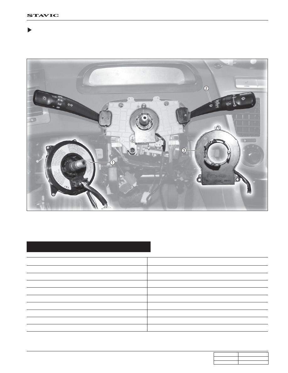
The steering wheel angle sensor is located between clock spring and multifunction switch. This sensor is used for
recognition of driver’s intends. If the sensor is replaced with new one, it can detect the neutral position after the vehicle
is moving over 20 km/h for more than 5 seconds.

1. Clock spring

2. Multi-function switch

3. SWAS (Steering Wheel Angle Sensor)

Specifications

Descriptions

Specifications

ABS/ESP SYSTEM

STAVIC - 2004.09

44

4K

CHANGED BY

EFFECTIVE DATE

AFFECTED VIN

LED

Phototransistor

Steering column

Slotted plate

The steering wheel angle sensor is integrated with the phototransistor and the LED and there is a slotted plate between
them. When the inner slotted plate rotates with the steering column shaft when the steering wheel is turned, the voltage
occurs through the holes. The detected voltage will be transmitted to the ESP unit as a pulse from the 3 terminals.

Then, the two voltage pulses are used to get the average value for detecting the steering wheel position and its angle
speed. And the other pulse is used for checking the alignment of the steering wheel.

Center line of steering wheel

Working voltage

Duty

Low - V

Number of pulse

per revolution

High - V

STN

Detects the center value
of steering wheel

ST1 and ST2

Detects steering wheel
angle and angular veloc-
ity as an average value

9 ~16 V

Approx. 50 %

1.3 ~ 2.0 V

45 Pulses /1rev

3.0 ~ 4.1 V

Steering wheel angle

sensor connector

Steering wheel angle

Steering

Wheel

Angle

Sensor

(SWAS)

ESP

unit

With ESP

ABS/ESP SYSTEM

STAVIC - 2004.09

45

4K

CHANGED BY

EFFECTIVE DATE

AFFECTED VIN

Sensor Cluster

The lateral sensor, logitudinal sensor and the yaw rate sensor are important components of the Electronic Stability
Program. The cluster links these sensors to an on-board computer unit and to a CAN interface, incased in a sturdy
housing, that is mounted on the chassis. Its modular concept allows the integration of further sensor functions.

Power supply

ECU

Power supply

circuit

Micro controller

(self diagnosis)

CAN module

Sensor cluster

A/D converter

Yaw rate sensor

Lateral sensor

Longitudinal sensor

CAN

Internal Electric Circuit of Sensor Cluster

Location

ABS/ESP SYSTEM

STAVIC - 2004.09

46

4K

CHANGED BY

EFFECTIVE DATE

AFFECTED VIN

Specification

Specifications

Approx. 8 ~ 16 V

Approx. 2.5 V (Ignition switch “ON”)

0.2 ~ 4.8 V

-75°/s ~ +75°/s

Descriptions

Supplying voltage

Output voltage when stop

Output range

Operation start speed

Sensor Cluster Circuit

(sensor cluster: yaw rate sensor + lateral acceleration sensor + Longitudinal acceleration sensor)

The yaw rate sensor relies on the action of micro-scopic tun-
ing forks. The plane in which these forks vibrate shifts when
the car turns around its vertical axis. This shift is evaluated
electronically.

A faulty yaw rate sensor produces an output signal of 0 V.

Yaw Rate Sensor

Power

Ground

Power

Sensor cluster

ESP unit


Content   ..  413  414  415  416   ..