SsangYong Stavic / SsangYong Rodius (2005 year). Service manual - part 224


  Index      SsangYong     SsangYong Stavic / SsangYong Rodius - service and repair manual 2005 year


Search            


Content   ..  222  223  224  225   ..


SsangYong Stavic / SsangYong Rodius (2005 year). Service manual - part 224


16

CHANGED BY

EFFECTIVE DATE

AFFECTED VIN

CLUSTER / WARNING & INDICATOR PANEL

RODIUS/STAVIC - 2005.07

2B

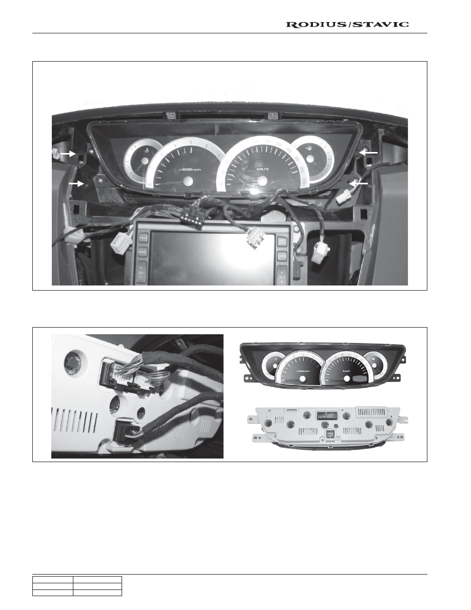
7. Unscrew four screws and pull out the meter cluster housing.

8. Disconnect the connector and remove the meter cluster housing.

17

CHANGED BY

EFFECTIVE DATE

AFFECTED VIN

CLUSTER / WARNING & INDICATOR PANEL

RODIUS/STAVIC - 2005.07

2B

2. Unscrew the screws and pull out the indicator display

housing.

Indicator Display

1. Remove the indicator display cover.

3. Disconnect the connector and remove the indicator

display housing.

3

CHANGED BY

EFFECTIVE DATE

AFFECTED VIN

RK STICS

STAVIC - 2004.09

2C

REKES + STICS (RK STICS)

The STICS in this vehicle has similar functions with the one used in other vehicle models. Additional function of diagnos-
ing through SCAN-I has been added into new STICS.

The major difference in hardware-wise is that receives automatic door unlock signal from airbag module through G-
sensor in RK STICS unit when the vehicle has collided over 15 km/h of vehicle speed.

1. COMPONENTS LOCATOR

STICS / ICM module

Air bag ECU

Sends the vehicle collision signals

to STICS.

Installed under the battery. This

horn works only for the theft deter-

rent function, panic function, and

remote starting.

Theft deterrent horn

This diagnosis connector is used for

S T I C S   k e y   c o d i n g   a n d   t r o u b l e

diagnosis.

Diagnosis connector

RK STICS

ICM module

This module contains

various relays, chime and

buzzer controlled by STICS

Added the escort and

panic function

REKES

4

CHANGED BY

EFFECTIVE DATE

AFFECTED VIN

RK STICS

STAVIC - 2004.09

2C

2. TRANSMITTER CODING

Coding process:

1. Remove the ignition key from key hole.

2. Connect the No. 3 terminal (REKES coding) and No. 16 terminal (battery+) on the diagnosis connector with a

jumper cable.

3. Press any button on the remote control key shortly. (approx. 0.5 sec.)

4. When the coding is successful, turn signal lamps blink once and warning horn sounds once.

5. If the coding has failed, repeat 1 to 4 steps.

Connector pin descriptions

1

3

5

7

9

11

13

15

2

4

6

8

10

12

14

16

-

REKES (for coding)

Signal ground

ECU

Air bag

TCU

TCCU

REKES (for diagnosis)

IG1

Ground

CAN_High

ABS

TGS

FFH (for diagnosis)

CAN_Low

Battery+


Content   ..  222  223  224  225   ..