SsangYong Stavic / SsangYong Rodius (2005 year). Service manual - part 212


  Index      SsangYong     SsangYong Stavic / SsangYong Rodius - service and repair manual 2005 year


Search            


Content   ..  210  211  212  213   ..


SsangYong Stavic / SsangYong Rodius (2005 year). Service manual - part 212


CHANGED BY

EFFECTIVE DATE

AFFECTED VIN

ELECTRICAL SYSTEM

RODIUS /STAVIC- 2005.07

14

2A

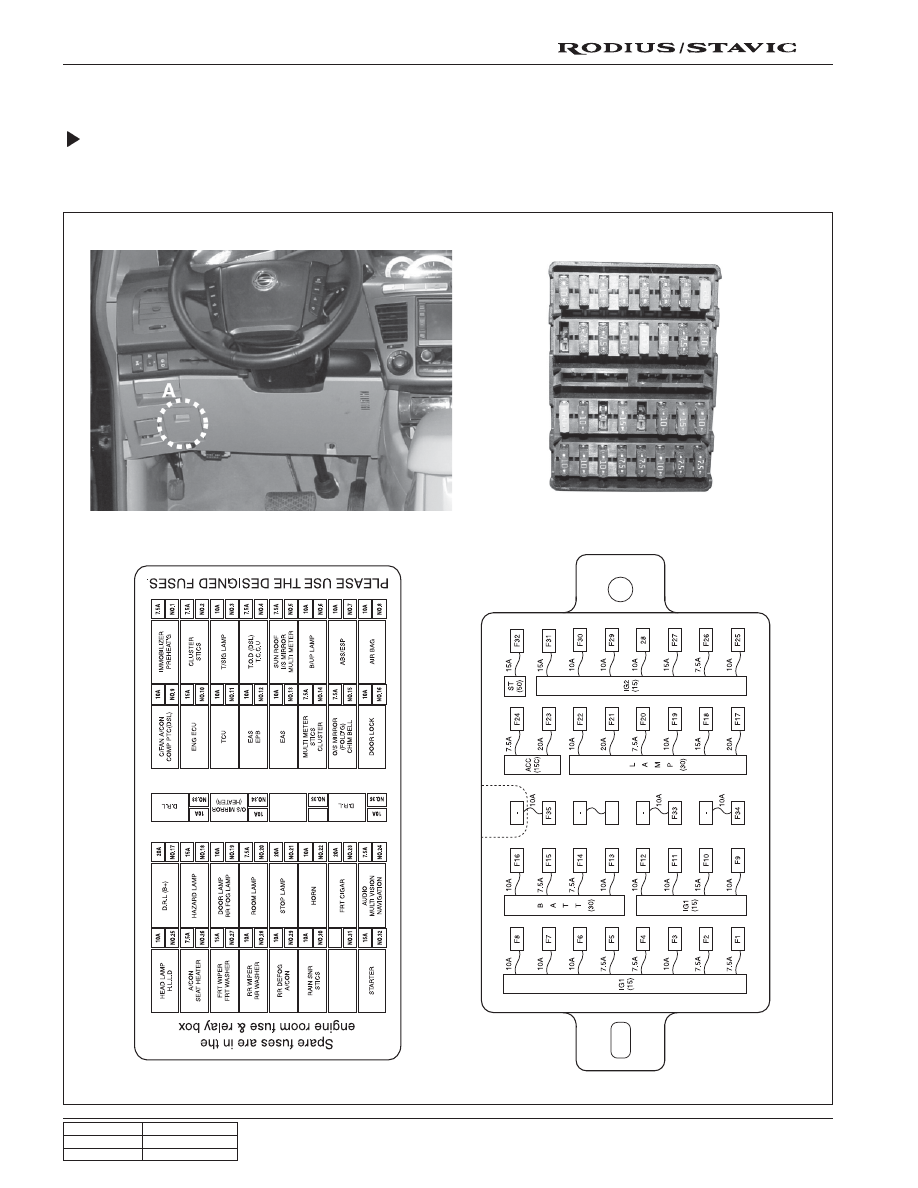
2. INTERIOR FUSE AND ICM BOX

Interior Fuse Box

• The interior fuse box is located in the lower area of driver side instrument panel.

• To check the fuses, open the driver side door and remove the fuse box cover.

CHANGED BY

EFFECTIVE DATE

AFFECTED VIN

ELECTRICAL SYSTEM

RODIUS /STAVIC - 2005.07

15

2A

ICM (Integrated Control Module) Box

The ICM box is installed along with RK STICS on the bracket behind the Instrument panel undercover.

It contains an integrated module with around 14 relays according to the vehicle model. Relays in the module are installed
on the integrated circuit with a safety circuit. This system operates with small current (by using transistor) and mini-
mizes the sparks that occur during operations (connection/disconnection) of relays; therefore its durability and wear
resistance has been greatly increased compared to the conventional relays.

Relays in the ICM box cannot be replaced respectively; so when the internal components (including relay) are defective,
ICM box should be replaced as an assembly.

ICM box

RK STICS

CHANGED BY

EFFECTIVE DATE

AFFECTED VIN

ELECTRICAL SYSTEM

RODIUS /STAVIC- 2005.07

16

2A

Printed Circuit Board Arrangement of ICM Box

The figure shows the internal arrangement of ICM box when the cover is removed and then disassembled.
The relays cannot be disassembled and replaced respectively; so the ICM box should be replaced as an
assembly when any internal components are defective.

Front view

Relay 1 (spare 2)

Relay 2

(O

2

 sensor: gasoline)

Relay 5

(wiper INT-LOW)

Relay 6

(wiper HIGH)

Relay 7

(power socket)

Relay 13

(theft deterrent relay)

Buzzer 1

(Back sonar)

Relay 15
(rear fog lamp)

Chime bell circuit

Relay 3
(seat warmer, LH)

Relay 4
(seat warmer, RH)

Relay 9
(horn relay)

Relay 14
(flasher unit)

Relay 10
(front cigarette lighter
and power socket)

Relay 11
(door unlock)

Relay 12
(driver’s door unlock)

Buzzer 2

Relay 8
(door lock relay)

CHANGED BY

EFFECTIVE DATE

AFFECTED VIN

ELECTRICAL SYSTEM

RODIUS /STAVIC - 2005.07

17

2A

Rear view

Relay 1

Relay 3

(spare 2)

Relay 4

Relay 2

Relay 5

Relay 6

Relay 7

Relay 13

Buzzer 1

Relay 14

Relay 10

Buzzer 2

Relay 9

Relay 8

Relay 12

Relay 11

Relay 15


Content   ..  210  211  212  213   ..