SsangYong Stavic / SsangYong Rodius (2005 year). Service manual - part 204


  Index      SsangYong     SsangYong Stavic / SsangYong Rodius - service and repair manual 2005 year


Search            


Content   ..  202  203  204  205   ..


SsangYong Stavic / SsangYong Rodius (2005 year). Service manual - part 204


CHANGED BY

EFFECTIVE DATE

AFFECTED VIN

ELECTRICAL SYSTEM

STAVIC - 2004.09

16

2A

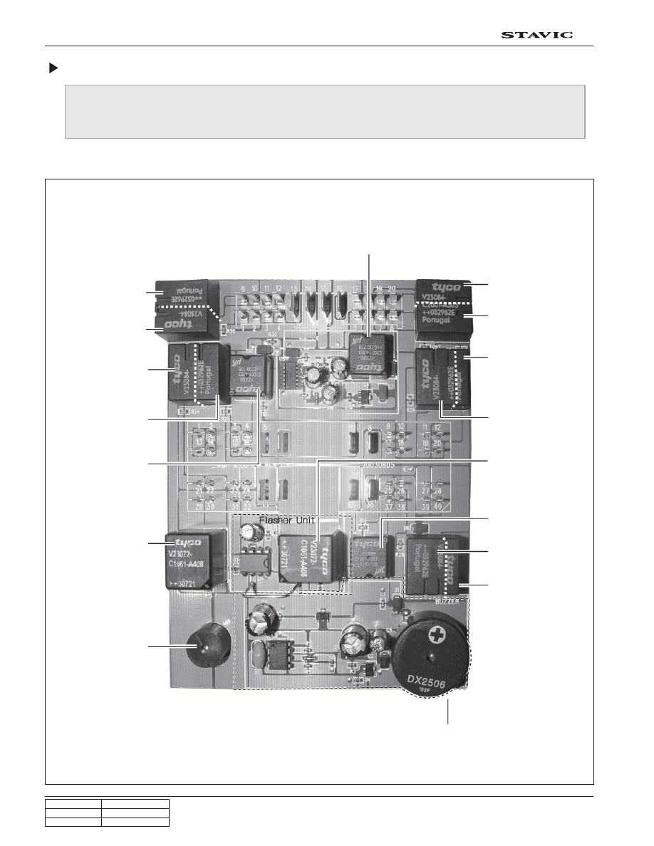
Printed Circuit Board Arrangement of ICM Box

The figure shows the internal arrangement of ICM box when the cover is removed and then disassembled.
The relays cannot be disassembled and replaced respectively; so the ICM box should be replaced as an
assembly when any internal components are defective.

Front view

Relay 1 (spare 2)

Relay 2

(O

2

 sensor: gasoline)

Relay 5

(wiper INT-LOW)

Relay 6

(wiper HIGH)

Relay 7

(power socket)

Relay 13

(theft deterrent relay)

Buzzer 1

(Back sonar)

Relay 15
(rear fog lamp)

Chime bell circuit

Relay 3
(seat warmer, LH)

Relay 4
(seat warmer, RH)

Relay 9
(horn relay)

Relay 14
(flasher unit)

Relay 10
(front cigarette lighter
and power socket)

Relay 11
(door unlock)

Relay 12
(driver’s door unlock)

Buzzer 2

Relay 8
(door lock relay)

CHANGED BY

EFFECTIVE DATE

AFFECTED VIN

ELECTRICAL SYSTEM

STAVIC - 2004.09

17

2A

Rear view

Relay 1

Relay 3

(spare 2)

Relay 4

Relay 2

Relay 5

Relay 6

Relay 7

Relay 13

Buzzer 1

Relay 14

Relay 10

Buzzer 2

Relay 9

Relay 8

Relay 12

Relay 11

Relay 15

CHANGED BY

EFFECTIVE DATE

AFFECTED VIN

ELECTRICAL SYSTEM

STAVIC - 2004.09

18

2A

ICM Connector Arrangement (Based on Wiring Connectors)

Never apply battery power from the rear of ICM printed circuit board directly to inspect internal circuit of the ICM box.
Otherwise, the precise internal circuits and safety circuit can be destroyed. When inspecting the power supply and
others, the connectors should be removed before starting the inspection.

The pin arrangements shown in the figure are also based on the connectors.

   ! "

! " # $
      !  "

 #  $  %  &

!% !& !' "

 ' ! ! ! 

% & '  

'    

# $

!! !"

!# !$

% &

CHANGED BY

EFFECTIVE DATE

AFFECTED VIN

ELECTRICAL SYSTEM

STAVIC - 2004.09

19

2A

ICM Box Power Supply Circuit

The figure shows ICM box power supply circuit. For details, refer to the appropriate wiring diagrams.

1) Door lock relay / Cigarette lighter relay / Power outlet relay

This circuit is supplied the power through the relevant fuse and STICS. The supplied power magnetize the switch to
supply the power to the appropriate system.

To inspect this circuit, turn the switch on and check if the voltage from ICM box is within specified range. After then,
check the output through the ICM box.

Checking the condition of the relevant component in the system should be done before doing this inspection.


Content   ..  202  203  204  205   ..