SsangYong Stavic / SsangYong Rodius (2005 year). Service manual - part 99


  Index      SsangYong     SsangYong Stavic / SsangYong Rodius - service and repair manual 2005 year


Search            


Content   ..  97  98  99  100   ..


SsangYong Stavic / SsangYong Rodius (2005 year). Service manual - part 99


DI03-9

CHANGED BY

EFFECTIVE DATE

AFFECTED VIN

INTAKE SYSTEM

DI ENG SM - 2004.9

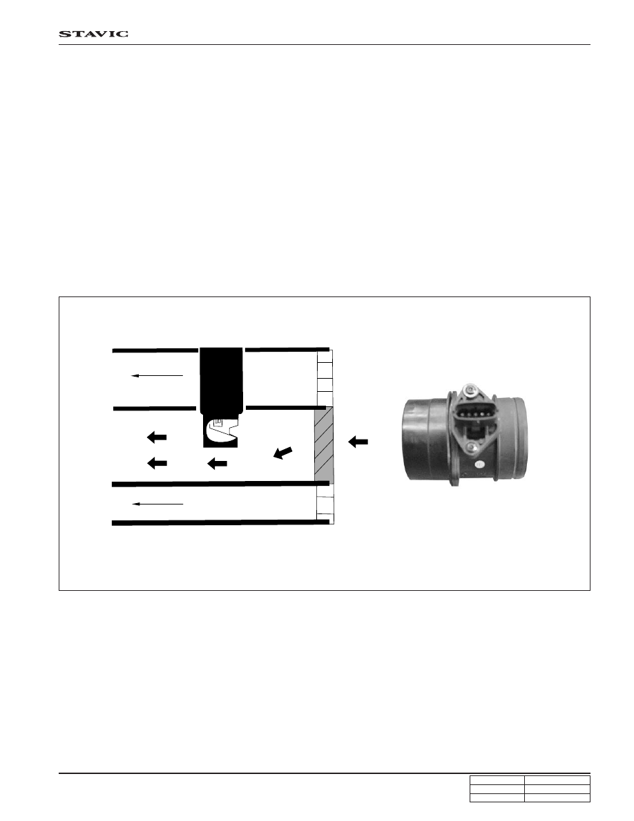
<Structure of CI type HFM sensor>

Intake air temperature sensor is a part of HFM sensor and a thermister and resister and detects air temperature
changes that flow into the engine. There occurs high resistance when temperature is low and low resistance when high
(NTC type).

ECU supplies 5 V to intake air temperature sensor and then measures voltage changes to determine the intake air
temperature. When air in the intake manifold is cold, the voltage is high and air is hot, the voltage is low.

The reason for using HFM sensor is that this sensor is most proper in controlling accurate air-fuel ratio to meet the legal
emission regulations. This sensor measures actual intake air mass into engine very accurately during specific instant
acceleration and deceleration, and determines engine loads and detects intake air pulsation and air flows.

Main functions of HFM sensor are:

• Using for EGR feedback control

• Using for turbocharger booster pressure control valve control

• Using for fuel injecting compensation

CI type HFM sensor: The air flowing the sensor does not directs toward sensing section but flows along with lower wall
after passing protection grid to enhance durability of the sensor. Oil, water and dust less damage the sensor.

Air outlet

Air inlet

DI03-10

CHANGED BY

EFFECTIVE DATE

AFFECTED VIN

INTAKE SYSTEM

DI ENG SM - 2004.9

<Circuit diagram of HFM sensor>

Power supply

Intake air
f l o w
sensor

Intake air temperature

sensor

HFM sensor

Signal

Ground

Ground

DI03-11

CHANGED BY

EFFECTIVE DATE

AFFECTED VIN

INTAKE SYSTEM

DI ENG SM - 2004.9

HFM sensor

HFM Sensor - Removal and Installation

Preceding Work: Disconnection of negative battery cable

1. Disconnect the HFM sensor connector.

2. Loosen the clamps on the air cleaner and the turbo

charger and remove the duct.

3. Unscrew the bolts and remove the HFM sensor assembly.

Installation Notice

Tightening torque

4 ~ 5 Nm

4. Install the reverse order of removal.

DI03-12

CHANGED BY

EFFECTIVE DATE

AFFECTED VIN

INTAKE SYSTEM

DI ENG SM - 2004.9

INTERCOOLER

The turbo charger is designed to improve the engine power by introducing more air (oxygen) into the engine. However,
the intake air is heated (100 ~ 110°C) during the compression process in turbo charger compressor and the density is
lowered.

The intercooler is the device which cools (50 ~ 60°C) the air entering the engine. Colder air has more oxygen molecules
than warm air. Thus cooler air gives more power and better fuel economy.

1. Intercooler


Content   ..  97  98  99  100   ..