Renault Kangoo Z.E. (2018 year). Manual - part 12
5.16
The bulbs are under pres-
sure and can break when
replaced.
Risk of injury.
Bulb type
4 Indicator
Pear-shaped, bayonet type bulb P
Y21W.
5 Side and brake light
Pear-shaped, bayonet type bulb
with two filaments P 21/5W.
6 Reversing light
Pear-shaped, bayonet type bulb P
21W.
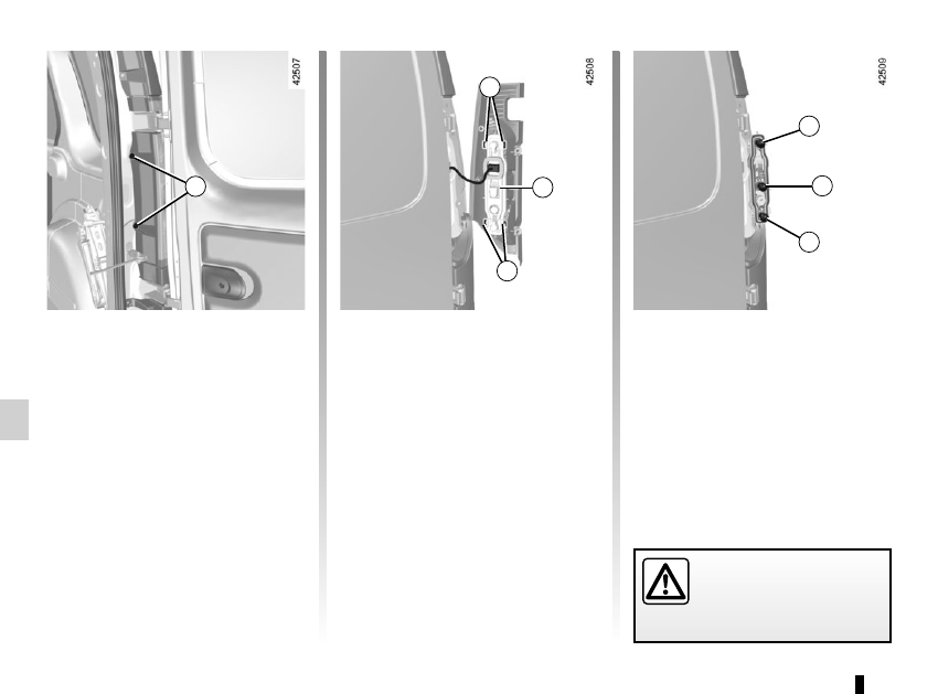
Rear lights
Depending on the vehicle, open the
hinged doors or the tailgate.
Undo bolts 1 using a Torx tool.
Unclip the lower section, then the upper
section of the light by pulling it towards
you.
Pull tabs 2 to unclip bulb holders 3.
Replace the bulb, then proceed in the
reverse order to refit the bulb.
REAR LIGHTS: changing bulbs
(1/3)
3
1
2
2
5
4
6