Dacia SuperNova (engine E7J). Service manual - part 18


  Index      Dacia     Dacia SuperNova (engine E7J) - service and repair manual 2004 year


Search            


Content   ..  16  17  18  19   ..


Dacia SuperNova (engine E7J). Service manual - part 18


ENGINE  E7J-A-2/60

12

FUEL MIXTURE

D

ISMO UNTING

The battery is disconnected.
The air tube is taken off the battery-protecting screen.
The four screws (1) for air-filter fixing are taken off.
The hose connecting the combustion-head cap and the air-filter is disconnected.
The air-filter is taken apart

To disconnect:

-the acceleration cable (the end of the cable is uncoupled from the command lever

of the clapper, and then it is taken off the sleeve on the stand);
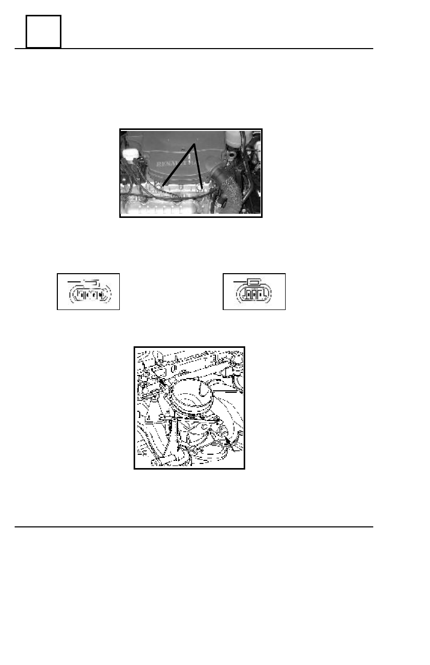
-the connectors:

 I. of the step-by-step engine;               II. of the clapper potentiometer.

R

E

-M

O UNTING

The fitting of the clapper body is replaced;
The same steps are taken as in the case of the dismantling, only in the reverse order.

12 - 4

1

I

II

CLAPPER BODY

(no. 2 clamp is pulled upwards and the connector is taken off)

The command lever is uncoupled off the body of the clapper;
The clapper body is taken apart.

2

2

ENGINE  E7J-A-2/60

12

FUEL MIXTURE

The following are taken apart:

- air-filter;
- acceleration cable;
- injection ramp (see Chapter Injec-

tion ramp);

The electric connectors are uncoupled:

- atmospheric pressure sensor;
- air temperature sensor;
- step-by-step engine;
- clapper potentiometer.

The fuel supply conduits are taken apart (both going- and return);
The clapper command lever is uncoupled and the body of the clapper is taken off;
The screws and screw-nuts fixing the intake collector are taken apart.

R

E

-M

O UNTING

The fittings of the intake collector are replaced;
The same steps are taken as in the case of the dismantling, only in the reverse order.
Tighten the inlet manifold screws and nuts at the required moment of 2.5 daNm.

T

IGH TENING


CO UPLE

  (daNm)

 Screws and screw-nuts for intake collector   2.5

INTAKE COLLECTOR

12 - 5

D

ISMOUNTING

ENGINE  E7J-A-2/60

12

FUEL MIXTURE


T

IGH TENING


CO UPLE

  (daNm)

  Screws for collector fixing       2.5

D

ISMO UNTING

The thermic screen is taken apart;
The connection between the exhaust collector and the exhaust pipe is taken off;
The exhaust collector is taken apart

Re-mounting

The same steps are taken as in the case of the dismantling, only in the reverse order.
The screws are tightened at the couple.

EXHAUST COLLECTOR

12 - 6

E7J-A-2/60 ENGINE

13

PUMP SUPPLY

A

IM

:

To avoid accidental fires owing to fuel leaks, which can be caused by an accident.

F

UNCTIONING

:

The shock-sensor lies in the engine compartment: it is mounted on the left-side shock-

absorber column.

During a shock, the ball of the sensor goes out of its slot, and thus achieves the breaking

of the electric circuit between the relay commanding the petrol-pump and the petrol-pump
itself.

P

LACING


BACK


TH E


SH OCK

-

SENSOR


IN


O PERATIONAL


MO DE

     In order to resume the functioning of the shock-sensor it will suffice to press its top,
and thus replace the ball in its former position.

BREAKING FUEL SUPPLY

13 - 1


Content   ..  16  17  18  19   ..