Dacia Pick-Up 1304/1305/1307. Service manual - part 88
36
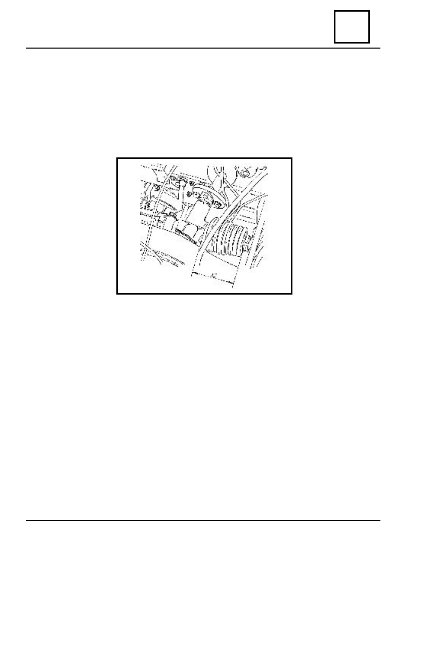
STEERING ASSEMBLY
In order to set the steering gear central point, bring the rack in the position in which the
value C = 65mm.
This position is obtained when a rivet of the elastic coupling is oriented upwards.
Performing of a checking and adjustment operation of the front axle, impose the
identification of the steering gear central point in order to avoid measurement errors
occurrence.
STEERING GEAR BOX
The replacement of the steering gear box implies the adjustment of the steering gear
height and the parallelism adjustment
D
ISMO UNTING
Disconnect the battery.
Dismount: the battery and the battery support.
Dismount the steering gear auxiliary connecting rods shaft nuts.
Remove the ball joints of the auxiliary connecting rods using the PF476 extractor.
Disconnect the steering auxiliary connecting rod connections with the steering box.
36 - 3
SETTING THE STEERING GEAR CENTRAL POINT