Dacia Pick-Up 1304/1305/1307. Service manual - part 27


  Index      Dacia     Dacia Pick-Up 1304/1305/1307 (Engine F8Q) - service and repair manual 2004 year


Search            


Content   ..  25  26  27  28   ..


Dacia Pick-Up 1304/1305/1307. Service manual - part 27


14

ANTIPOLLUTION

D

ISMO UNTING

Disconnect the ( - ) terminal of the battery.
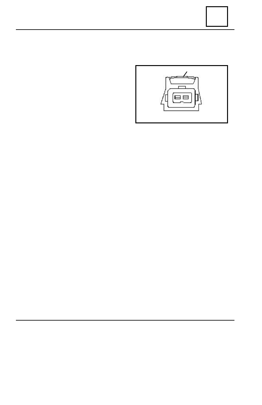
Disconnect the connector of coupling

the fuel injection control wiring to the
purging valve, pushing the lock (1),after that
disconnecting the connector.

Dismount the fixing clips of the hoses to

the purging valve and disconnect the hoses.

R

EMO UNTING

14 - 3

Perform in reverse order the dismounting operations.
The can purging valve shall be mounted so that the arrow marked on its body to be

oriented from the can to the injector valve body.

1

CARBON CAN VALVE

16

STARTING AND CHARGING

16 - 1

   The Dacia pick-up vehicles can be equipped with following types of alternators:

   For vehicles of Dacia range, there are used alternators type 1114.200 and type 1180

(used for vehicles provided with AC).

CHECKING ON BENCH

( for alternator type 1114.200 )

LOAD CHARACTERISTIC

     General electric diagram:

I = f (n); U = ct = 13,5 V

  RPM

I

NTENSITY

[ rot/min ]

[ A ]

N

1

1300

I


>  11

N

2

3000

I

>  43

N

3

5000

I

> 47

N

4

8000

I

4


> 52

N

5  

    12 500

I

5

  > 50

N

N

6000

I

N


> 40

The checking tests of the values for alternator type 1114,which are measures at

N 4 rpm, are performed when engine is cold.
    The checking of the values at rpm N1N2N3N5, are performed when the engine is
warm, i.e. after the alternator has been working for about one hour on voltage14 +/ -  0,1  V.
     After measuring the value of the current at rpm N5 ,adjust the exciter voltage at
10 +/- 0,1 V and the voltage at the plugs level at 14 + / - 0,1 V. Adjust  rpm  NN at
6000 +/- 60 rpm and measure the corresponding value of the current, as soon as it is
stabilized.

Type of alternator

        1114.200

1180

Operating voltage

12V

12V

Ampere rating in stable operating conditions


50 A

80 A

Maximum excitation current

3,9 A

5 A

Maximum power

700 W

1100 W

Type of relay used

           1410;1342           electronic

        electronic

 incorporated

ALTERNATOR

STARTING AND CHARGING

16

16 - 2

ALTERNATOR CHECKING

( for alternator type 1180 )

 The general electric diagrams and the curves of the load characteristic of the alternator

type 1180 are the followings:

A. CHECKING OF THE CURRENT INTENSITY

A

 - Unstable operating conditions

B

 - Stable operating conditions

Tip 1114. 200

Tip 1180

 GENERATOR ROTATION SPEED


(rot/min)

 GENERATOR ROTATION SPEED


(rot/min)

ALTERNATOR

16

STARTING AND CHARGING

16 - 3

LOAD CHARACTERISTIC

I = f ( n ); U = ct = 13,5 V

RPM 

REGIM

   [ rot/min ]

           C

ORRESPONDING


INTENSITY

 [ A ]

N

0

N

1

N

2

N

3

N

4

N

max.

1200
1250

1500+/- 1%
3000+/- 1%
6000+/- 1%
12500+/- 1%

I

0

I

1

I

2

I

3

I

4

max.

> 0
> 10
> 20
> 43
> 48
> 50

B. CHECKING OF THE ADJUSTED VOLTAGE

For checking the adjusted voltage, perform an assembly similar to next diagram.

   After starting the engine, accelerate until rpm is 300 rot/min then increase the alternator
current from 10 A to 43 A ; the voltage must be between 13,8 and 14,5 V, at a temperature
of  22 ° +/- 5 ° C.
   If this condition is not accomplished, check the voltage; if also this is correct, replace the
electronic regulator and check again. If defect persists, check by dismounting, the alternator
components.

ALTERNATOR


Content   ..  25  26  27  28   ..