Peugeot 308 SW BL Dag (2009.5). Manual - part 11


  Index      Peugeot     Peugeot 308 SW BL Dag 2009.5 - service manual in english


Search            


Content   ..  9  10  11  12   ..


Peugeot 308 SW BL Dag (2009.5). Manual - part 11


11

i

165

PRACTICAL INFORMATION

  This  repair  kit  is  available  from 
PEUGEOT dealers. 
 It is designed to repair most punc-
tures which could affect the tyre, lo-
cated on the tyre tread or shoulder. 
Avoid removing any foreign bodies 
which have penetrated the tyre.   

TEMPORARY 
PUNCTURE REPAIR 
KIT 

 The kit is stowed in the boot below the 

fl oor. It is fi tted in the tool box, located 

below the storage compartment. 
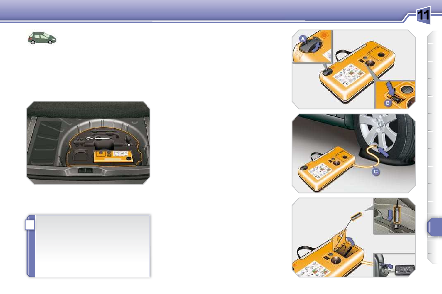
  Using the kit 

 This  procedure,  comprising  several 
steps, must be carried out in full. 
      Switch off the ignition. 
     Turn the selector  A  to the "SEALANT" 

position. 

     Check  that  the  switch   B   is  in 

position  "0" . 

     Connect  the  white  pipe   C   to  the 

valve of the tyre to be repaired. 

     Connect  the  compressor's  electric 

plug to the vehicle's 12 V socket. 

  

   Affi x  the  speed  limitation  sticker 

to  the  vehicle's  steering  wheel 
to  remind  you  that  a  wheel  is  in 
temporary use. 

     Start  the  vehicle  and  leave  the 

engine running. 

  Access to the kit 

 Complete  system  consisting  of  a  com-
pressor  and  an  incorporated  sealant 
cartridge  which  permits   temporary  re-
pair
  of the tyre so that you can drive to 
the nearest garage. 

11

i

i

166

PRACTICAL INFORMATION

  If  after  around  5  to  7  minutes  the 
pressure  is  not  attained,  this  indi-
cates that the tyre is not repairable; 
contact a PEUGEOT dealer for as-
sistance.  

     Switch on the compressor by moving 

the switch  B  to position  "1"  until the 
tyre pressure reaches 2.0 bars. 

     Remove the kit, taking care to avoid 

to  avoid  staining  your  vehicle  with 

traces of fl uid. Keep the kit to hand. 

  

   Drive immediately for approximately 

three  miles  (fi ve  kilometres),  at 

reduced  speed  (between  15  and 

35  mph  [20  and  60  km/h]),  to  plug 

the puncture. 

     Stop to check the repair and the tyre 

pressure using the kit.  

      Turn  the  selector   A   to  the  AIR 

position. 

     Connect  the  black  pipe   D   to  the 

valve of the wheel. 

  You can use this kit for the routine 
check  and  adjustment  of  the  tyre 
pressures  on  your  vehicle.  It  can 

also be used to infl ate other items 

such as a ball or bicycle tyre.   
To  do  this,  turn  the  selector  to  the 
"AIR"  position,  connect  the  black 
pipe  with  the  appropriate  adapter 

to the item to be infl ated, then fol-

low the remainder of the procedure 
below until the kit is removed.  

11

i

!

!

167

PRACTICAL INFORMATION

   Tyre under-infl ation detection 

 If the vehicle is fi tted with tyre under-

infl ation detection, the under-infl ation 

warning lamp will remain on after the 
wheel has been repaired until the sys-
tem  is  reinitialised  by  a  PEUGEOT 
dealer.   

  Take  care,  this  product  is  harmful 
(e.g.  ethylene-glycol,  colophony, 

ethanediol...)  if  swallowed  and 

causes irritation to the eyes. Keep 

it out of reach of children. 
   The expiry date of the fl uid is indi-

cated on the cartridge.
The  sealant  cartridge  is  designed 
for  single  use;  even  if  only  partly 
used, it must be replaced. 
 To remove the cartridge, unscrew it 
completely at its cap and pull off. 
 After  use,  do  not  discard  the  car-
tridge  into  the  environment,  take 
it  to  an  authorised  waste  disposal 
site or a PEUGEOT dealer. 
 Do  not  forget  to  obtain  a  new 
sealant  cartridge,  available  from 
PEUGEOT dealers.   

     Connect  the  compressor's  electric 

plug to the vehicle's 12 V socket. 

     Start the vehicle again and leave the 

engine running. 

     Adjust  the  pressure  using  the 

compressor  (to  infl ate:  switch   B   in 

position   "1"

 ;  to  defl ate:  switch   B  in 

position  "0"  and press button  E

 ), in 

accordance  with  the  vehicle's  tyre 
pressure  label  (located  on  the  left 

hand door aperture).


A loss of pressure indicates that the 
puncture has not been fully plugged; 
contact  a  PEUGEOT  dealer  for 
assistance.   

     Remove and stow the kit. 

     Drive  at  reduced  speed  (50  mph 

[80 km/h] max) limiting the distance 

travelled to approximately 120 miles 

(200 km). 

     Go  to  a  PEUGEOT  dealer  as 

soon as possible.  


Have  the  tyre  inspected  by  a 
technician, who can then advise 
you  whether  it  can  be  repaired 
or should be replaced.  

11

i

168

PRACTICAL INFORMATION

 This  repair  kit  is  available  from 
PEUGEOT dealers. 
 It  is  designed  to  repair  holes  of  a 

maximum diameter of 6 mm, locat-

ed exclusively on the tyre tread or 

shoulder.  Avoid  removing  any  for-
eign bodies which have penetrated 
the tyre. 

TEMPORARY TYRE 
REPAIR KIT 

 Complete system consisting of a compres-
sor  and  a  bottle  of  sealant  which  permits 
 temporary  repair   of  the  tyre  so  that  you 
can drive to the nearest garage. 

 The  kit  is  installed  in  the  boot  storage 
tray. 

  Using the kit 

      Switch off the ignition. 
     Tick the wheel to be repaired on the 

speed  limitation  sticker  enclosed 

then affi x the sticker to the vehicle's 

steering wheel to remind you that a 
wheel is in temporary use. 

     Clip the bottle  1  on the compressor  2 . 

     Check  that  the  switch   A   is  tilted  to 

position  "0" . 

     Connect  the  pipe  of  the  bottle   1   to 

the valve of the tyre to be repaired. 

     Unwind the pipe of the compressor  2  

fully, then connect it to the bottle. 

     Connect  the  compressor's  electric 

plug to the vehicle's 12 V socket. 

     Start  the  vehicle  and  leave  the 

engine running. 

11

i

169

PRACTICAL INFORMATION

If  this  pressure  has  not  been 

reached after approximately fi ve to 

ten minutes, the tyre cannot be re-
paired; contact a PEUGEOT dealer 
to have your vehicle repaired. 

     Switch  on  the  compressor  by  tilting 

the switch  A  to position  "1"  until the 
tyre pressure reaches 2.0 bars.  

     Remove  the  compressor  and  store 

the bottle in the plastic bag, supplied 
in  the  kit,  to  avoid  staining  your 

vehicle with traces of fl uid. 

  

   Drive immediately for approximately 

two  miles  (three  kilometres),  at 

reduced  speed  (between  10  and 

35 mph [20 and 60 km/h]), to fi ll the 

puncture. 

     Stop  to  check  the  repair  and  the 

pressure. 

     Connect 

the 

compressor 

pipe 

directly  to  the  valve  of  the  repaired 
wheel. 

11

i

!

!

170

PRACTICAL INFORMATION

 If the vehicle is fi tted with tyre under-

infl ation  detection,  the  tyre  under-

infl ation warning light will remain on 

after  the  wheel  has  been  repaired 
until the system is reinitialised by a 
PEUGEOT dealer.  

 Take  care,  the  bottle  of  fl uid  con-

tains  ethylene-glycol.  This  product 
is harmful if swallowed and causes 

irritation to the eyes. Keep it out of 

reach of children. 
 The expiry date of the fl uid is indi-

cated on the base of the bottle.  
The bottle is designed for a single 
use; even if only partly used, it must 
be replaced. 
 After use, do not discard the bottle 
into  the  environment,  take  it  to  a 
PEUGEOT  dealer  or  to  an  organi-
sation  responsible  for  its  collec-
tion. 
 Do  not  forget  to  obtain  a  new  bot-

tle of fi lling product, available from 

PEUGEOT dealers. 

     Connect  the  compressor's  electric 

plug  to  the  vehicle's  12 V  socket 
again. 

     Start the vehicle again and leave the 

engine running. 

     Adjust  the  pressure  using  the 

compressor  (to  infl ate:  switch   A   in 

position   "1"

 ;  to  defl ate:  switch   A  in 

position   "0"   and  press  button   B

 ), 

in  accordance  with  the  vehicle's 
tyre  pressure  label  (located  on  the 

door  aperture  on  the  driver's  side), 

then  remember  to  check  that  the 

leak  is  fi lled  correctly  (no  further 

loss  of  pressure  after  several  miles 

[kilometres]). 

     Remove the compressor, then store 

the whole kit. 

     Visit  a  PEUGEOT  dealer  as 

soon  as  possible  to  have  the 
tyre  repaired  or  replaced  by  a 
technician.  

     Drive  at  reduced  speed  (50  mph 

[80  km/h]  max)  for  no  more  than 

approximately 125 miles (200 km). 

11

i

171

PRACTICAL INFORMATION

CHANGING A WHEEL 

 The tools are installed in the boot under 

the fl oor. 

 To gain access to them: 
      open the boot, 
  

   raise the fl oor, 

     secure it by hooking its cord on the 

hook on the rear shelf support, 

  

   unclip and remove the box containing 

the tools.  

 All of these tools are specifi c to your 

vehicle.  Do  not  use  them  for  other 
purposes. 
   1.   Wheelbrace.  
 

For removal of the wheel trim and 

removal of the wheel fi xing bolts. 

  2.   Jack with integral handle.  
 

For raising the vehicle. 

  3.   Socket  for  the  security  bolts 

(located in the glove box).  


For adaptation of the wheelbrace 
to the special security bolts.   

  List of tools 

  Access to the tools 

  Wheel with trim 
  When removing the wheel

 , detach the trim fi rst using the wheelbrace  1  pulling 

at the valve passage hole. 
  

When refi tting the wheel , refi t the trim starting by placing its notch facing the 

valve and press around its edge with the palm of your hand.   

 Procedure  for  changing  a  faulty  wheel 
for the spare wheel using the tools pro-
vided with the vehicle. 

11

i

i

172

PRACTICAL INFORMATION

  Fixing the steel spare wheel 
 If  your  vehicle  is  fi tted  with  alloy 

wheels, it is normal to notice, when 

tightening  the  bolts  on  fi tting,  that 

the washers do not come into con-
tact with the steel spare wheel. The 
wheel  is  secured  by  the  conical 
contact of each bolt.  

  Access to the spare wheel 

 The spare wheel is installed in the boot 

under the fl oor. 
 According  to  country,  the  spare  wheel 
may be steel or alloy. 
 To gain access to it, refer to the paragraph 
"Access  to  the  tools"  on  the  previous 
page. 

  Taking out the wheel 
      Unscrew the yellow central bolt. 
     Raise the spare wheel towards you 

from the rear. 

     Take the wheel out of the boot.   

  Putting the wheel back in place 
      Put the wheel back in its housing. 
     Unscrew the yellow central bolt by a 

few  turns  then  put  it  in  place  in  the 
centre of the wheel. 

     Tighten  fully  until  the  central  bolt 

clicks to retain the wheel correctly. 

  

   Put  the  box  back  in  place  in  the 

centre of the wheel and clip it.   

  Tyre under-infl ation detection 

 The spare wheel is not fi tted with 

a  sensor.  The  punctured  wheel 
must be repaired  by a PEUGEOT 
dealer.   

11

i

173

PRACTICAL INFORMATION

CHANGING A WHEEL 

 Procedure  for  changing  a 
faulty  wheel  for  the  spare 
wheel  using  the  tools  pro-
vided with the vehicle. 

 The wheelbrace  1  is installed in the boot 
left-hand side trim. 
 The tools  2  and  3

  are installed in a box, 

in the centre of the spare wheel, placed 
underneath the vehicle. 
 To gain access to them: 
      open the boot, 
  

   open the access fl ap in the left-hand 

side trim, 

     remove  the  wheelbrace  from  its 

support, 

     refer  to  the  paragraph  "Access  to 

the  spare  wheel"  on  the  next  page 

to retrieve the other tools.  

  Access to the tools 

  List of tools 

  Wheel with trim 
  When removing the wheel

 , detach the trim fi rst using the wheelbrace  1  pulling 

at the valve passage hole. 
  

When refi tting the wheel , refi t the trim starting by placing its notch facing the 

valve and press around its edge with the palm of your hand.   

 All  of  these  tools  are  specifi c  to  your 

vehicle. Do not use them for other pur-
poses. 
   1.   Wheelbrace.  
 

For removal of the wheel trim and 

removal of the wheel fi xing bolts. 

  2.   Jack with integral handle.  
 

For raising the vehicle. 

  3.   Socket  for  the  security  bolts 

(located in the glove box).  


For  adaptation  of  the  wheelbrace 
to the special security bolts.   

11

i

174

PRACTICAL INFORMATION

  Fixing the steel or "space-
saver" type spare wheel 
 If  your  vehicle  is  fi tted  with  alloy 

wheels, it is normal to notice, when 

tightening  the  bolts  on  fi tting,  that 

the washers do not come into con-
tact with the steel or "space-saver" 
type  spare  wheel.  The  wheel  is 
secured  by  the  conical  contact  of 
each bolt.  

  Access to the spare wheel 

 The spare wheel is supported by a winch 
system underneath the vehicle. 
 According  to  country,  the  spare  wheel 
may  be  steel,  alloy  or  of  the  "space-
saver" type. 

  Taking out the wheel  

   

   Open the fl ap with the eye to release 

the  winch  and  access  its  control 
nut. 

     Unscrew  this  nut  fully,  using  the 

wheelbrace   1 ,  to  unwind  the  winch 
cable. 

  

   Detach  the  wheel/box  assembly 

from the rear of the vehicle. 

     Take  out  the  hook  to  release  the 

wheel/box  assembly,  as  shown  in 

the illustration. 

     Take  out  the  black  plastic  centring 

cone. 

     Take out the wheel to gain access to 

the box. 

  

   Slide  the  box  cover  to  the  centre 

and remove it to gain access to the 
other tools.  

11

i

i

175

PRACTICAL INFORMATION

  Tyre under-infl ation detection 

 The  spare  wheel  is  not  fi tted  with 

a  sensor.  The  punctured  wheel 
must  be  repaired  by  a  PEUGEOT 
dealer.  

  Putting the wheel back in place 
      Store the corresponding tools in the 

box and close the cover. 

  

   Position the box on the ground and 

centre the spare wheel on it. 

     Position  the  black  plastic  centring 

cone (on the steel or "space-saver" 

type wheel only). 

  

   Pass the hook into the box cover. 

  

   Raise  the  wheel/box  assembly 

underneath the vehicle by tightening 
the  winch  control  nut  using  the 
wheelbrace  1 . 

     Tighten  fully  and  check  that  the 

wheel  is  horizontally  fl ush  against 

the fl oor. 

  

   Close  the  fl ap  with  the  eye  to  lock 

the winch.  

 If you purchase a wheel of standard 
size  to  replace  the  "space-saver" 
type  spare  wheel,  the  spacer,  lo-
cated underneath the vehicle, must 
be removed. Consult a PEUGEOT 
dealer.   

11

i

176

PRACTICAL INFORMATION

  Parking the vehicle 
 Immobilise  the  vehicle  where  it 

does  not  block  traffi c:  the  ground 

must be level, stable and non-slip-
pery ground. 
 Apply the parking brake, switch off 

the ignition and engage fi rst gear *  

to lock the wheels. 
 If  necessary,  place  a  chock  under 
the  wheel  diagonally  opposite  the 
wheel to be changed. 
 It is imperative that you ensure that 
the occupants get out of the vehicle 
and wait where they are safe. 
 Never  go  underneath  a  vehicle 

raised  using  a  jack;  use  an  axle 

stand.  

          Removing the wheel 

  List of operations 
      Fit  the  security  socket   3   on  the 

wheelbrace  1  to slacken the security 
bolt. 

     Slacken  the  other  bolts  using  the 

wheelbrace  1  only. 

     Place  the  jack   2   in  contact  with  one 

of  the  two  front   A   or  rear   B   locations 
provided on the underbody, whichever 
is closest to the wheel to be changed. 

  

   Extend the jack  2  until its base plate 

is in contact with the ground. Ensure 
that  the  centreline  of  the  jack  base 
plate is directly below the location  A  
or  B  used. 

     Raise  the  vehicle  until  there  is 

suffi cient space between the wheel 

and  the  ground  to  admit  the  spare 

(not punctured) wheel easily. 

     Remove the bolts and store them in 

a clean place. 

     Remove the wheel.    


*    position   R   for  the  piloted  manual 

gearbox;  P  for the automatic gear-

box.  

11

i

177

PRACTICAL INFORMATION

  After changing a wheel 
 To store the punctured wheel in the 

boot correctly, fi rst remove the cen-

tral cover. 
 When  using  the  "space-saver"  type 

spare wheel, do not exceed 50 mph 

(80 km/h). 
 Have the tightening of the bolts and 
the  pressure  of  the  spare  wheel 
checked  by  a  PEUGEOT  dealer 
without delay. 
 Have the punctured wheel repaired 
and  replace  it  on  the  vehicle  as 
soon as possible.  

  Fitting the wheel 

  List of operations 
      Put the wheel in place on the hub. 
     Screw  in  the  bolts  by  hand  to  the 

stop. 

     Pre-tighten  the  security  bolt  using 

the  wheelbrace   1

   fi tted  with  the 

security socket  3 . 

     Pre-tighten the other bolts using the 

wheelbrace  1  only. 

     Lower the vehicle fully. 
     Fold the jack  2  and detach it. 

     Tighten  the  security  bolt  using  the 

wheelbrace  1

  fi tted with the security 

socket  3 . 

     Tighten  the  other  bolts  using  the 

wheelbrace  1  only. 

  

   Store the tools in the box.    

11

!

!

!

178

PRACTICAL INFORMATION

  Risk of electrocution 
 Xenon  bulbs  (D1S-35W)  must  be 

replaced by a PEUGEOT dealer.   

CHANGING A BULB 

 Procedure for replacing a faulty bulb with a 
new bulb without the use of tools. 

        Model with halogen headlamps 

   1.    Direction indicators 

(PY   21W   amber).  

  2.    Dipped   beam   headlamps 

(H7     -     55W).  

  3.    Main beam headlamps (H1     -     55W).  
  4.    Daytime   running lamps/

    sidelamps   (P 21/  5W  ).  

  5.    Foglamps   (H8     -     35W).     

   1.    Direction indicators 

(PY 21W SV silver).  

  2.    Directional dipped/main beam 

headlamps (D1S-35W).  

  3.    Additional main beam headlamps 

(H1-55W).  

  4.    Daytime running lamps/

sidelamps (P 21/5W).  

  5.    Foglamps (H8-35W).    

                             Model with xenon and directional 
headlamps 

 The headlamps are fi tted with poly-

carbonate  glass  with  a  protective 

coating: 
       do not clean them using a dry 

or  abrasive  cloth,  nor  with  a 
detergent or solvent product,
  

     use a sponge and soapy water, 
     when  using  a  high  pressure 

washer  on  persistent  marks, 
do  not  direct  at  the  lamps  or 
their outlines for too long, so as 
not  to  damage  their  protective 
coating and seals.  

       Do  not  touch  the  bulb  directly 

with  your  fi ngers,  use  lint-free 

cloths.  

 Changing  a  halogen  bulb  should 
only  be  done  after  the  headlamp 
has  been  switched  off  for  a  few 

minutes (risk of serious burns). 
 It is imperative to use only anti-ul-

traviolet  (UV)  type  bulbs  in  order 

not to damage the headlamp.  

  Front lamps  

11

i

!

179

PRACTICAL INFORMATION

                 Changing main beam headlamp 
bulbs 
      Remove  the  protective  cover  by 

pulling on the tab. 

     Disconnect the bulb connector. 
     Compress the springs to release the 

bulb. 

     Remove the bulb and change it  
 To refi t, carry out these operations in re-

verse order.  

  Changing daytime running lamp/
sidelamp bulbs 
      Remove  the  protective  cover  by 

pulling on the tab. 

     Disconnect the bulb connector. 
     Turn  the  bulb  holder  a  quarter  of  a 

turn and extract it. 

     Pull the bulb and change it.  
 To refi t, carry out these operations in re-

verse order.  

        Changing dipped beam headlamp 
bulbs 
      Remove  the  protective  cover  by 

pulling on the tab. 

     Disconnect the bulb connector. 
     Spread  the  springs  to  release  the 

bulb. 

  

   Extract the bulb and change it.  

 To refi t, carry out these operations in re-

verse order.   

   Changing direction indicator bulbs 

      Turn  the  bulb  holder  a  quarter  of  a 

turn and extract it. 

     Pull the bulb and change it.  
 To refi t, carry out these operations in re-

verse order. 

 Amber  or  silver  coloured  bulbs, 
such  as  the  direction  indicators, 
must  be  replaced  with  bulbs  of 

identical specifi cations and colour. 

 When refi tting, close the protective 

cover carefully to assure the seal-
ing of the headlamp.   

11

180

PRACTICAL INFORMATION

        Changing foglamp bulbs 

      Insert  a  screwdriver  towards  the 

centre  of  the  repeater  between  the 
repeater and the base of the mirror. 

  

   Tilt  the  screwdriver  to  extract  the 

repeater and remove it. 

     Disconnect the repeater connector.  
 To refi t, carry out these operations in re-

verse order. 
 Contact  a  PEUGEOT  dealer  to  obtain 
replacement repeaters.   

  Changing integrated direction 
indicator side repeaters 

 To  replace  these  bulbs  consult  a 
PEUGEOT dealer.   


Content   ..  9  10  11  12   ..