Peugeot 307 CC (2007.5). Manual - part 8


  Index      Peugeot     Peugeot 307 CC 2007.5 - service manual in english


Search            


Content   ..  6  7  8  9   ..


Peugeot 307 CC (2007.5). Manual - part 8


10

97

PRACTICAL INFORMATION

   Access to the spare wheel and 
the jack in the boot 
   

   Place  the  vehicle  in  the  coupé 

position. 

     Detach the luggage retaining net. 
     Lift the boot mat using the handle.     
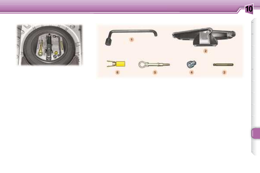
   Tools 
 The  following  tools  are  located  in 

a  holder  in  the  centre  of  the  spare 

wheel: 
   1.   Wheelbrace. 
  2.

   Jack with handle. 

  3.   Centralising tool. 
  4.   Socket for anti-theft bolt. 
  5.

   Removable towing eye. 

  6.

   Alloy wheel bolt trim remover.  

 A diagram on the holder indicates the 
location of the tools.    

   Parking the vehicle 
   

   As  far  possible,  park  the  vehicle 

on level, stable and non-slippery 

ground. 

  

   Apply the handbrake, àswitch off 

the  ignition  and  engage  i rst  or 

reverse  gear  (position   P   for  the 

automatic gearbox).    

  CHANGING A WHEEL   

10

98

PRACTICAL INFORMATION

   Extracting the wheel 

   Removing the wheel 
   

   If necessary, place a chock under 

the  wheel  diagonally  opposite  to 

the one to be changed. 

  

   Remove  the  trim,  using  the 

wheelbrace  1 , pulling at the valve 

passage hole. 

  

   Loosen the wheel bolts (for vehi-

cles  i tted  with  alloy  wheels,  re-

move the chrome trims i rst. See 

paragraph on "Special features of 

alloy wheels"). 

  

   Place  the  jack   2   in  contact  with 

one of the four locating points  

 on the sub-frame, the one which 

is  closest  to  the  wheel  to  be 

changed. 

  

   Extend  the  jack   2   until  its  base 

is in contact with the ground. En-

sure  that  the  centre  line  of  the 

base of the jack is directly below 

the locating point  A  used. 

   Fitting a wheel  
   

   Position  the  wheel  using  the 

centralising tool   to assist you. 

     Tighten  the  bolts  by  hand  and 

remove the centralising tool. 

     Partly  tighten  the  bolts  using  the 

wheelbrace  1 . 

  

   Fold the jack  2  and remove it. 

     Fully  tighten  the  bolts  using  the 

wheelbrace  1 .  

  

   Replace  the  wheel  trim,  starting 

by  placing  the  wheel  trim  notch 

opposite  the  valve,  and  press  it 

on using the palm of the hand.     

     Raise the vehicle. 
  

   Unscrew  the  bolts  and  remove 

the wheel.     

   

   Unscrew the yellow central bolt a 

quarter turn. 

  

   Raise  the  spare  wheel  towards 

you from the rear. 

  

   Remove  the  wheel  from  the 

boot.   

10

i

!

!

99

PRACTICAL INFORMATION

   Putting the wheel back in 
place 

   

   Put the wheel back in place.  

   

   Unscrew the yellow central bolt a 

few  turns,  then  put  it  in  place  in 

the centre of the wheel. 

     Tighten the central bolt fully until it 

clicks to secure the wheel i rmly. 

     Put  the  tool  holder  back  in  the 

centre of the wheel and clip it. 

  

   Put the boot l oor back in place.   

Wheels i tted with the Tyre Under-

Inl ation Detection system
 For further information refer to "Tyre 

under-inl ation  detection"  in  the 

safety section.   

 The  wheel  must  be  positioned 

l at, in the centre of its housing. 

   After changing the wheel: 
   -  

have  the  tightening  of  the 

bolts  and  the  tyre  pressure 

checked  by  a  PEUGEOT 

dealer as soon as possible, 

  -   have  the  punctured  tyre 

repaired and rei t it to the ve-

hicle as soon as possible.    

   Recommendations when 
using the temporary spare 
wheel *  
 Your  vehicle  may  be  equipped 

with  a  spare  wheel  with  a  rim 

which is different from that of the 

standard wheel. 

 After  use,  be  sure  to  replace  it 

as soon as possible. 

 Observe  the  following  instruc-

tions  to  avoid  altering  the  han-

dling of the vehicle: 
   -  

do  not  drive  above   50  mph 
(80 km/h)

 , 

  -   do not i t a wheel trim, 

  -   drive carefully, 

  -   check  the  inl ation  pressure 

indicated on the label.     

   For your safety, always 
change the wheel: 
   -   on level, stable, non-slippery 

ground, 

  -   with  the  handbrake  on  and 

the ignition switched off, 

  -   with  i rst  or  reverse  gear 

engaged  (position   P   for  the 

automatic gearbox), 

  -   with the vehicle chocked.  
  Never  go  underneath  a  vehi-
cle  that  is  supported  only  by 
a jack (use a ramp).
    

   *    According to model and country.   

10

100

PRACTICAL INFORMATION

 Alloy  wheel  bolts  are  covered  by 

chrome trims. 
 Use the yellow tool  6  to remove the 

trims before slackening the bolts.   

 If  your  vehicle  is  i tted  with  a  steel 

spare wheel, when i tting it, it is  nor-

mal

  when tightening the bolts to no-

tice  that  the  washers  do  not  come 

into  contact  with  the  rim. The  spare 

wheel is secured by the cone shape 

of each bolt.   

   Anti-theft bolts 

 If your wheels are i tted with an anti-

theft bolt (one per wheel), the chrome 

trim  must  be  removed  before  un-

screwing the bolt using the anti-theft 

socket and the wheelbrace. 

 This  anti-theft  socket  was  given  to 

you on delivery of your vehicle along 

with the duplicate keys and the con-

i dential card. 
 Make  a  careful  note  of  the  code 
number engraved on the head of the 

anti-theft socket. This will enable you 

to  obtain  a  duplicate  socket  from  a 

PEUGEOT dealer.   

   Fitting snow tyres 
 If you i t snow tyres mounted on steel 

wheels  onto  your  vehicle,  it  is   es-

sential

  to use special bolts available 

from your PEUGEOT dealer.    

   Special features of alloy wheels  

   Bolt covers 

   Fitting the spare wheel 

10

i

101

PRACTICAL INFORMATION


In  the  engine  compartment,  on  the 

right-hand side, remove the style trim * : 

   -   press  the  centre  of  each  plastic 

stud  A

 , 

  -   remove each plastic stud, 
  -  

remove the style trim.  

 When  you  have  i nished,  do  not 

forget to put everything back in place 

correctly: 

   -   position the style trim * , 
  -  

rei t each plastic stud  A  by pressing 

on it.   

   1.  Dipped beam headlamps

(H1-55 W or xenon bulb). 

  WARNING:  RISK  OF  ELECTRO-
CUTION
  
 Xenon  bulbs  must  be  changed  by  a 
PEUGEOT dealer.   
   2.  Main beam headlamps 

(H7-55 W). 

   

   Remove  the  protective  cover 

corresponding to the faulty bulb. 

     Disconnect the connector.  
     Press  the  end  of  each  securing 

clip. Change the bulb.  

 When  i tting  the  new  bulb,  ensure 

that  the  direction  notches  are  po-

sitioned  correctly  and  the  securing 

clips are i xed properly. 

      Reconnect the connector. 
  

   Rei t the protective cover.  

  CHANGING A BULB  

   Front lights 


Handle the bulbs with a dry cloth. 

 The  headlamps  are  i tted  with 

polycarbonate glass with a pro-

tective  coating.   Do  not  clean 
them  with  a  dry  or  abrasive 
cloth, nor  with a  detergent  or 
solvent product. 
  
 Use a sponge and soapy water.   

  *    According to engine.   

10

i

102

PRACTICAL INFORMATION

   

   Push  the  repeater  forwards  and 

release it. 

    

Remove the repeater and change it.  

 These  can  be  obtained  from  a 
PEUGEOT dealer. 

   3.  Side lights (W 5 W). 
   

   Remove  the  protective  cover 

corresponding to the faulty bulb. 

     Disconnect the connector. 
     Remove the bulb and change it.    
   4.  Direction indicators 

(PY 21 W amber). 

   

   Turn the bulb holder a quarter of 

a turn and remove it. 

     Change the bulb.  

  Note :  in  certain  climatic  conditions 

(low temperature, humidity),  conden-

sation inside the headlamp glass is 
normal

 ; it disappears a few minutes 

after the lights are switched on.   

 Contact a PEUGEOT dealer to have 
these bulbs changed.   

   5.  Fog lamps (H11-55 W). 

   Integrated direction indicator side 
repeaters. 

 Amber  coloured  bulbs,  such  as 

the direction indicators, must be 

replaced  with  bulbs  of  identical 

specii cation and colour.    

10

!

103

PRACTICAL INFORMATION

   

   Unclip the corresponding boot lid 

trim at two points. 

     Move  the  trim  aside  gently  to 

access the bulb holder  6 . 

  

   Unscrew  the  bulb  holder  a 

quarter of a turn. 

     Remove the bulb holder. 
     Change the faulty bulb.  
  Note:

   when  rei tting,  take  care  to 

position  the  bulb  holder  correctly.   

   1.    Brake lights (diodes).  
  2.    Side lights (diodes).  
  3.    Direction indicators (P 21 W).  
  4.    Reversing light (P 21 W), left 

side.   


Fog lamp (P 21 W), right side.   

      Remove  the  3  bolts  of  the  corre-

sponding  boot  side  trim  to  access 

the light (use the 20 Torx

TM

 adaptor 

of  tool   C   located  in  the  handbook 

pocket). 

  

   Remove the light i xing nut inside 

the boot. 

     Remove the light. 
  

   Unscrew  the  bulb  holder   5   a 

quarter of a turn. 

     Remove the bulb holder. 
     Change the faulty bulb.  
  Note:

  when rei tting, take care to po-

sition  the  bulb  holder  and  the  light 
correctly.  

  Rear lights 

  Direction indicators 

  Reversing light/fog lamp 

 All work on the diode lights must 

be  carried  out  by  a  PEUGEOT 
dealer. 

10

!

104

PRACTICAL INFORMATION

   

   Insert a thin screwdriver into one 

of the external holes of the lens. 

  

   Push it outwards to unclip it. 

     Remove the lens. 
     Change the faulty bulb.   

  Third brake light (diodes) 

  Number plate lights (W 5 W) 

 All work on the diode lights must 

be  carried  out  by  a  PEUGEOT 
dealer.  

10

105

PRACTICAL INFORMATION

 CHANGING A FUSE 

 The  fuse  boxes  are  placed  in  the 

glove  box  (passenger  side)  and  in 

the  engine  compartment  (left-hand 

side). 

  Correct  

  Incorrect   

 Open the glove box lid to gain access 

to the fuses. 

  Replacing a fuse 

 Before replacing a fuse, the cause of 

the incident must be found and recti-

i ed. The fuse numbers are indicated 

on the fuse box. 
 

Always replace a faulty fuse with a fuse 

of the same rating (same colour). 
 Use the special pliers located on the 

inside  of  the  fascia  fuse  box  cover, 

this  support  also  contains  the  re-

placement fuses. 

  Fascia fuses 

   Fuse N°   

   Rating   

   Functions   

   F36   

   20 A   

 Hi-Fi amplii er. 

   F40   

   30 A   

 Retractable roof pump supply. 

10

106

PRACTICAL INFORMATION

   Fuse N°   

   Rating   

   Functions   

   F1   

   -   

 Not used. 

   F2   

   30 A   

 Locking and deadlocking. 

   F3   

   5 A   

 Air bags and pre-tensioners unit. 

   F4   

   10 A   

 Brake and clutch pedal switches, engine coolant level switch, steering wheel angle sensor, 

diagnostic socket, ESP sensor, particle emission i lter pump, electrochromatic mirror. 

   F5   

   30 A   

 Front electric windows and heated mirrors supply. 

   F6   

   30 A   

 Rear electric windows supply, hinged l aps motor. 

   F7   

   5 A   

 Front and rear courtesy lights, map reading lights, glove box light. 

   F8   

   20 A   

 Multifunction display supply, audio equipment, audio/telephone, alarm siren, alarm control 

unit, trailer fuse box, steering wheel controls supply. 

   F9   

   30 A   

 12 V front socket, 12 V rear socket. 

   F10   

   15 A   

 Automatic gearbox control unit, brake switch, tyre under-inl ation detection control unit. 

   F11   

   15 A   

 Diagnostic socket, particle emission i lter control unit, low current ignition switch. 

   F12   

   15 A   

 Rear parking assistance, Hi-Fi amplii er. 

   F13   

   5 A   

 Engine fuse box supply, rain and brightness sensor. 

   F14   

   15 A   

 Trailer fuse box, instrument panel, automatic air conditioning, air bags, pre-tensioners and 

rear protective pop-up roll-over hoops unit, hands-free kit. 

   F15   

   30 A   

 Locking and deadlocking supply. 

   F16   

   -   

 PARC shunt. 

   F17   

   40 A   

 Heated rear screen. 

10

107

PRACTICAL INFORMATION

  Engine compartment fuses  

 To  access  the  fuses  located  in  the 

engine  compartment  (next  to  the 

battery), unclip the fuse box lid. 

 When you have i nished, close the lid 

carefully  to  guarantee  the  sealing  of 
the fuse box. 

   Fuse N°   

   Rating   

   Functions   

   F1   

   20 A   

 Fan assembly relay control, engine control unit control. 

   F2   

   15 A   

 Horn. 

   F3   

   10 A   

 Front wash-wipe. 

   F4   

   20 A   

 Headlamp wash. 

   F5   

   15 A   

 Fuel pump and purge canister solenoid valve (2 litre petrol). 

   F6   

   10 A   

 Four speed automatic gearbox control unit, automatic gearbox lever locking control, push 

control switch, fan assembly high speed relay, right and left xenon bulb headlamps. 

   F7   

   10 A   

 ABS/ESP control unit, power steering control unit. 

10

PRACTICAL INFORMATION

   F8   

   20 A   

 Starter control. 

   F9   

   10 A   

 Additional heating unit (Diesel), engine coolant level switch. 

   F10   

   30 A   

 Engine management actuators (ignition coil, solenoid valves, oxygen sensors, control units, 

injectors, heaters), purge canister solenoid valve (1.6 litre petrol). 

   F11   

   40 A   

 Air conditioning blower. 

   F12   

   30 A   

 Windscreen wipers low/high speed. 

   F13   

   40 A   

 Built-in systems interface supply (ignition positive). 

   F14   

   30 A   

 Air pump (2 litre petrol). 

   F15   

   10 A   

 Right main beam headlamp. 

   F16   

   10 A   

 Left main beam headlamp. 

   F17   

   15 A   

 Left dipped headlamp. 

   F18   

   15 A   

 Right dipped headlamp. 

   Fuse N°   

   Rating   

   Functions   

10

!

109

PRACTICAL INFORMATION

   Fuse N°   

   Rating   

   Functions   

   MF1 *    

   30 A   

 200 W fan unit. 

   50 A   

 400 W and 460 W fan unit. 

   MF2 *    

   30 A   

 ABS/ESP pump. 

   MF3 *    

   30 A   

 ABS/ESP solenoid valves. 

   MF4 *    

   80 A   

 Built-in systems interface supply. 

   MF5 *    

   80 A   

 Built-in systems interface supply. 

   MF6 *    

   80 A   

 Passenger compartment fuse box. 

   MF8 *    

   70 A   

 Power steering electro-pump unit. 

  *   

The maxi-fuses provide additional protection for the electrical systems. All work must be carried out by a PEUGEOT dealer.  

 The electrical system of your vehicle is designed to operate with standard or optional equipment. 

 Before installing other electrical equipment or accessories on your vehicle, contact a PEUGEOT dealer. 

 PEUGEOT will not accept responsibility for the cost incurred in repairing your vehicle or for rectifying the malfunctions 

resulting  from  the  installation  of  accessories  not  supplied  and  not  recommended  by  PEUGEOT  and  not  installed 

in accordance with its instructions, in particular when the combined consumption of all of the additional equipment 

connected exceeds milliamperes.  

10

!

110

PRACTICAL INFORMATION

   Special front windscreen 
wiper position 

   

   Within one minute of switching off 

the  ignition,  operate  the  wipers 

stalk to position the wiper blades 

in  the  centre  of  the  windscreen 

(maintenance position).    

   Changing a wiper blade 

   

   Lift the wiper arm, then unclip the 

blade and remove it. 

  

   Fit the new blade and push back 

the arm.  

  Note:

  the shortest blade is i tted on 

the  vehicle’s  right-hand  windscreen 

wiper arm. 
  To  return  the  windscreen  wipers  to 
their normal position, switch on the 
ignition and operate the wiper stalk.
    

  BATTERY  

   To charge the battery using a 
battery charger: 

   -  

Disconnect  the  battery  starting 

with the negative (-) terminal, 

  -   Follow  the  instructions  for  use 

given by the battery charger man-

ufacturer, 

  -  

Check  that  the  terminals  and 

connectors are clean; if they are 

covered  with  sulphate  (white  or 

greenish  deposit),  disconnect 

them and clean them, 

  -  

Reconnect  the  battery  starting 

with the negative (-) terminal.    

  It is advisable to disconnect the 
battery if the vehicle is not to be 
used  for  a  period  of  more  than 
one month.
  

   To start the vehicle from 
another battery: 

   -  

Connect  the  red  cable  to  the 

positive  (+)  terminals  of  the  two 

batteries, 

  -  

Connect  one  end  of  the  green 
or black cable to the negative (-) 

terminal of the slave battery, 

  -  

Connect the other end of the green 

or black cable to an earth point on 

the broken down vehicle as far as 

possible from the battery, 

  -   Operate the starter, let the engine 

run, 

  -  

Wait for the engine to return to idle, 

then disconnect the cables.  

  CHANGING A WINDSCREEN 
WIPER BLADE  

 Before  disconnecting  the  bat-

tery, you must wait for 2 minutes 

after switching off the ignition. 
 Never  disconnect  a  terminal 

when the engine is running. 
 

Never  charge  a  battery  without 

i rst disconnecting the terminals. 
 

Close  the  windows,  the  retract-

able  roof  and  the  doors  before 
disconnecting  the  battery.  If  the 

windows do not operate normally 

following reconnection of the bat-

tery,  they  must  be  reinitialised 

(see  sections  "Reinitialisation  of 

the electric windows" and "Reini-

tialisation of the automatic partial 

opening of the door windows"). 
 After  every  reconnection  of  the 

battery,  switch  on  the  ignition 

and wait 1 minute before starting 

to  allow  the  electronic  systems 

to be initialised. If slight difi cul-

ties  are  experienced  after  this, 

please  contact  a  PEUGEOT 

dealer. 
 Following  disconnection  of  the 

battery,  the  remote  control  key 

and  the  GPS  satellite  naviga-
tion system must be reinitialised 

(see corresponding section). 


Content   ..  6  7  8  9   ..