Nissan 240SX - Automatic Transmission (Section AT) (2000 year). Manual - part 10
Diagnostic Procedure
=NMAT0216
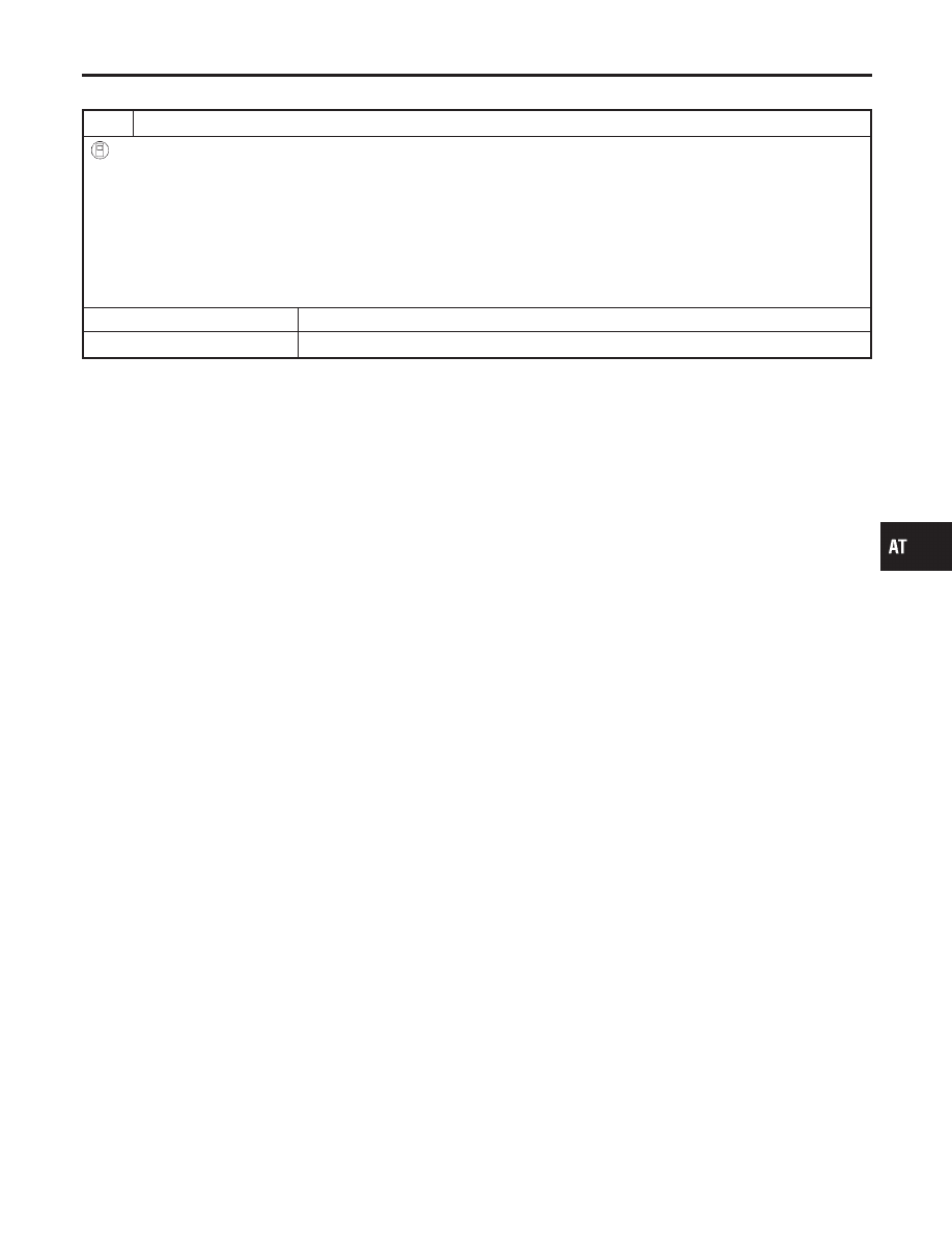
1
CHECK DTC
With CONSULT-II
1. Turn ignition switch “ON” and select “SELF DIAG RESULTS” mode for A/T with CONSULT-II.
2. Move selector lever to “R” position.
3. Depress accelerator pedal (Full throttle position).
4. Touch “ERASE”.
5. Turn ignition switch “OFF” position for 10 seconds.
Perform Self-diagnosis Code confirmation procedure.
See previous page.
Is the “CONT UNIT (EEPROM)” displayed again?
Yes
©
Replace TCM.
No
©
INSPECTION END
GI
MA
EM
LC
EC
FE
CL
MT
PD
AX
SU
BR
ST
RS
BT
HA
SC
EL
IDX
TROUBLE DIAGNOSIS FOR CONTROL UNIT (EEPROM)
Diagnostic Procedure
AT-145