Nissan Xterra (2015 year). Manual - part 8


  Index      Nissan     Nissan Xterra - service manual 2015 year in english


Search            copyright infringement  


Content   ..  6  7  8  9   ..


Nissan Xterra (2015 year). Manual - part 8


The front seats are warmed by built-in heaters.

1. Start the engine.

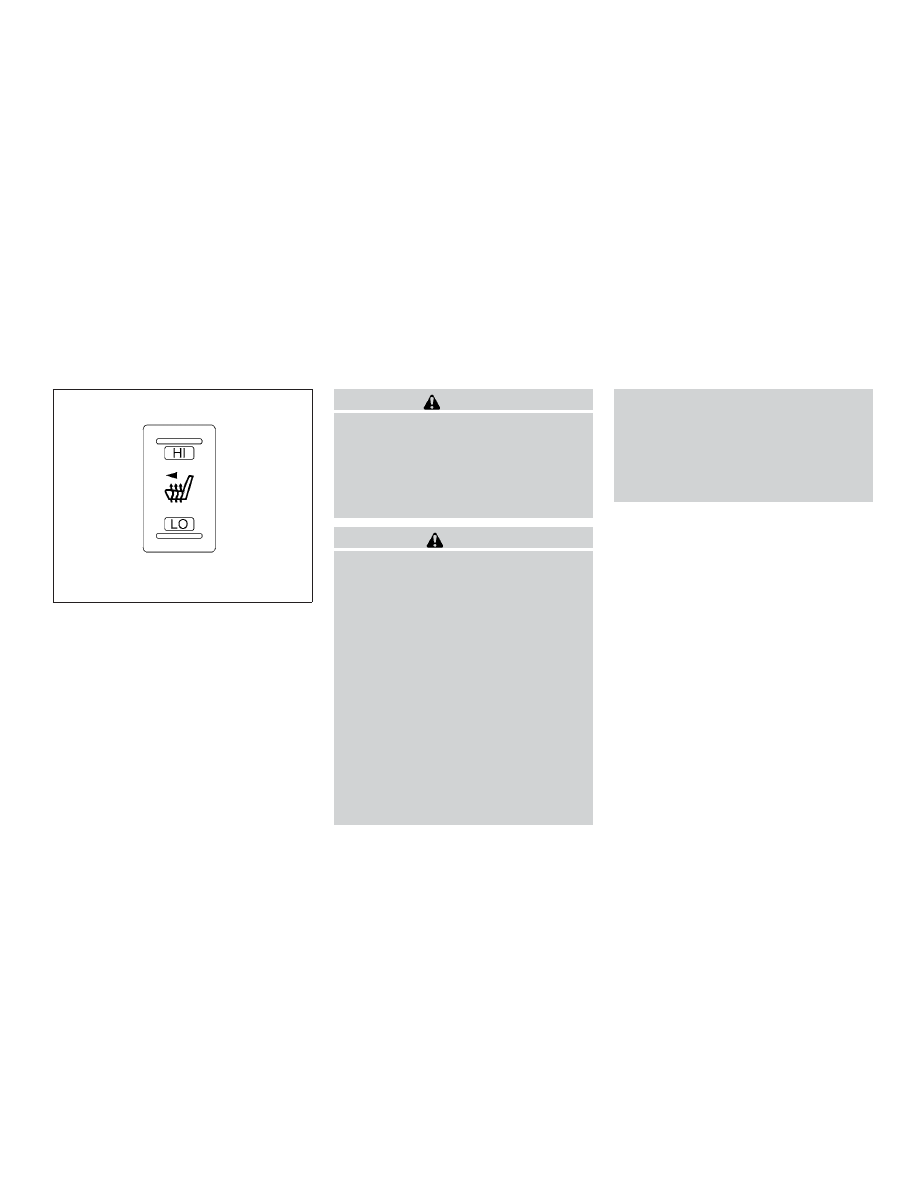
2. Push the LO or HI position of the switch, as

desired. The indicator light in the switch will
illuminate.

The heater is controlled by a thermostat,
automatically turning the heater on and off.
The indicator light will remain on as long as
the switch is on.

3. When the seat is warmed or before you

leave the vehicle, be sure to turn the switch
off.

WARNING

Do not use or allow occupants to use the
seat heater if you or the occupants cannot
monitor elevated seat temperatures or
have an inability to feel pain in body parts
that contact the seat. Use of the seat
heater by such people could result in seri-
ous injury.

CAUTION

● The battery could run down if the seat

heater is operated while the engine is
not running.

● Do not use the seat heater for extended

periods or when no one is using the
seat.

● Do not put anything on the seat which

insulates heat, such as a blanket, cush-
ion, seat cover, etc. Otherwise, the seat
may become overheated.

● Do not place anything hard or heavy on

the seat or pierce it with a pin or similar
object. This may result in damage to the
heater.

● Any liquid spilled on the heated seat

should be removed immediately with a
dry cloth.

● When cleaning the seat, never use

gasoline, benzine, thinner, or any simi-
lar materials.

● If any malfunctions are found or the

heated seat does not operate, turn the
switch off and have the system checked
by your NISSAN dealer.

LIC1543

HEATED SEATS (if so equipped)

Instruments and controls

2-33

The vehicle should be driven with the VDC sys-
tem on for most driving conditions.
If the vehicle is stuck in mud or snow, the VDC
system reduces the engine output to reduce
wheel spin. The engine speed will be reduced
even if the accelerator is depressed to the floor. If
maximum engine power is needed to free a stuck
vehicle, turn the VDC system off.
To turn off the VDC system, push the VDC OFF
switch. The

indicator will come on.

Push the VDC OFF switch again or restart the
engine to turn on the system. For additional infor-
mation, refer to “Vehicle Dynamic Control (VDC)
system” in the “Starting and driving” section of
this manual.

WARNING

● Never rely solely on the hill descent

control system to control vehicle speed
when driving on steep downhill grades.
Always drive carefully when using the
hill descent control system and deceler-
ate the vehicle speed by depressing the
brake pedal if necessary. Be especially
careful when driving on frozen, muddy
or extremely steep downhill roads. Fail-
ure to control vehicle speed may result
in a loss of control of the vehicle and
possible serious injury or death.

● The hill descent control may not control

the vehicle speed on a hill under all load
or road conditions. Always be prepared
to depress the brake pedal to control
vehicle speed. Failure to do so may re-
sult in a collision or serious personal
injury.

CAUTION

When the hill descent control system op-
erates continuously for a long time, the
temperature of the brake pads may in-
crease and the hill descent control system
may be temporarily disabled (the indicator
light will blink). If the indicator light does
not come on continuously after blinking,
stop using the system.

The hill descent control system is designed to
reduce driver workload when going down steep
hills. The hill descent control system helps to
control vehicle speed so the driver can concen-
trate on steering the vehicle.

To activate the hill descent control system:

● the 4WD switch must be in the 4L position

and the vehicle speed must be under
15 MPH (25 km/h) or

LIC1548

LIC0743

VEHICLE DYNAMIC CONTROL (VDC)
OFF SWITCH

HILL DESCENT CONTROL SWITCH (if
so equipped)

2-34

Instruments and controls

● the 4WD switch must be in the 4H position

and the vehicle speed must be under
21 MPH (35 km/h), and

● the hill descent control system switch must

be ON.

The hill descent control system on indicator light
will come on when the system is activated. Also,
the stop/tail lights illuminate while the hill descent
control system applies the brakes to control ve-
hicle speed.

If the accelerator or brake pedal is depressed
while the hill descent control system is on, the
system will stop operating temporarily. As soon
as the accelerator or brake pedal is released, the
hill descent control system begins to function
again if the hill descent control operating condi-
tions are fulfilled.

The hill descent control system on indicator light
blinks if the switch is on and all conditions for
system activation are not met or if the system
becomes disengaged for any reason.

To turn off the hill descent control system, push
the switch to the OFF position.

For additional information, refer to “Hill descent
control system on indicator light” in this section
and “Hill descent control system” in the “Starting
and driving” section of this manual.

The Electronic Locking Rear Differential (E-Lock)
system can help provide added traction if the
vehicle is stuck or becoming stuck.

To activate the E-Lock system:

● the 4WD switch must be in the 4LO position

(4-wheel drive vehicles),

● the vehicle must be stopped or moving at

4 MPH (7 km/h) or less, and

● the E-Lock system switch must be turned

ON.

When the E-Lock switch is turned ON, the indi-
cator light will flash until the system engages.
However, if all operation conditions listed above
are not met or the system becomes disengaged,
the indicator light will continue to flash.

The Anti-Lock Brake (ABS) system is disabled
and the ABS light illuminates when the E-Lock
system is ON. Also, the Vehicle Dynamic Control
(VDC) system is disabled and the VDC light
illuminates when the E-Lock system is ON.

For additional information, refer to “Electronic
locking rear differential (E-Lock) system” in the
“Starting and driving” section of this manual for
further explanation and system limitations.

WARNING

● Never leave the E-Lock system ON when

driving

on

paved

or

hard-surfaced

roads. Turning the vehicle may result in
the rear wheels slipping and result in an
accident and personal injury. After us-
ing the E-Lock system to free the ve-
hicle, turn the system OFF.

LIC0729

ELECTRONIC LOCKING REAR
DIFFERENTIAL (E-Lock) SYSTEM
SWITCH (if so equipped)

Instruments and controls

2-35

● Use the E-Lock system only when free-

ing a stuck vehicle. Try the 4LO position
before using the E-Lock system. Never
use the E-Lock system on a slippery
road surface such as snow or ice sur-
face. Using the E-Lock system when
driving in these road conditions may
cause unexpected movement of the ve-
hicle during engine braking, accelerat-
ing or turning, which may result in an
accident and serious personal injury.

CAUTION

● After using the E-Lock system, turn the

switch OFF to prevent possible damage
to driveline components from extended
use.

● Do not drive over 12 MPH (20 km/h)

when the system is engaged. Doing so
could result in possible damage to the
driveline.

● Do not turn on the E-lock system while

the tires are spinning. Doing so could
damage drivetrain components.

WARNING

Pay special attention to your surroundings
when using the clutch interlock switch.
The vehicle will move forward or backward
according to the gear selected.

The clutch interlock (clutch start) switch allows
for starting the engine without depressing the
clutch pedal. This feature helps you restart the
engine if it stops under difficult conditions. (For
example, the engine stops on a steep hill and a
slight movement forward or backward might be
dangerous.)

To use the clutch interlock switch:

1. Set the parking brake.

2. Depress the brake pedal with your right foot.

3. Place your left foot on the brake pedal and

release the parking brake.

4. Turn the ignition switch to the ON position.

5. Press and release the clutch interlock

switch. The CANCEL light on the switch will
illuminate.

6. Turn the ignition to the START position to

start the engine and, at the same time, de-
press the accelerator pedal with your right
foot. As the vehicle begins to move, take
your left foot off the brake. Once the engine
has started, the clutch interlock switch
CANCEL light shuts off. Do not use the
interlock switch to start the engine under
normal driving conditions.

WIC0817

CLUTCH INTERLOCK (clutch start)
SWITCH (if so equipped)

2-36

Instruments and controls

The power outlets are for powering electrical
accessories such as cellular telephones. They
are rated at 12 volt, 120W (10A) maximum.

The power outlets are powered only when the
ignition switch is in the ACC or ON position.

Open the cap to use a power outlet.

CAUTION

● The outlet and plug may be hot during

or immediately after use.

● Only certain power outlets are designed

for use with a cigarette lighter unit. Do
not use any other power outlet for an
accessory lighter. See your NISSAN
dealer for additional information.

● Do not use with accessories that exceed

a 12 volt, 120W (10A) power draw.

● Do not use double adapters or more

than 1 electrical accessory.

● Use power outlets with the engine run-

ning to avoid discharging the vehicle
battery.

● Avoid using power outlets when the air

conditioner, headlights or rear window
defroster is on.

● Before inserting or disconnecting a

plug, be sure the electrical accessory
being used is turned OFF.

● Push the plug in as far as it will go. If

good contact is not made, the plug may
overheat or the internal temperature
fuse may open.

● When not in use, be sure to close the

cap. Do not allow water or any other
liquids to contact the outlet.

Front row

LIC2872

Center console

LIC0761

Luggage area

LIC0862

POWER OUTLET

Instruments and controls

2-37

STORAGE TRAYS

WARNING

Do not place sharp objects in the trays to
help prevent injury in an accident or sud-
den stop.

Top center tray

LIC1539

A/T model (if so equipped)

LIC0818

M/T model (if so equipped)

WIC1421

STORAGE

2-38

Instruments and controls

CONSOLE BOX

Pull up on the lever

1

to open the console box lid

2

.

GLOVE BOX

To open the top portion of the glove box, push the
latch

A

up and raise the lid.

To open the lower portion of the glove box, pull
the handle

B

down and lower the lid.

Use the master key to lock or unlock the glove
box. The valet key cannot be used to lock or
unlock the glove box.

WARNING

Keep glove box lid closed while driving to
help prevent injury in an accident or a
sudden stop.

SUNGLASSES HOLDER

To open the sunglasses holder, push and release.

WARNING

● Keep the sunglasses holder closed

while driving to prevent an accident.

LIC0766

LIC0768

WIC0609

Instruments and controls

2-39

CAUTION

● Do not leave sunglasses in the sun-

glasses holder while parking in direct
sunlight. The heat may damage the
sunglasses.

● Do not use for anything other than

sunglasses.

MAP POCKETS

SEAT POCKETS (if so equipped)

A pocket is located on the back of the driver’s
seat.

LIC0863

LIC0575

2-40

Instruments and controls

CUP HOLDERS

The front cup holders have adapters that can be
removed to accommodate larger cups.

CAUTION

● Avoid abrupt starting and braking when

the cup holder is being used to prevent
spilling the drink. If the liquid is hot, it
can scald you or your passenger.

● Use only soft cups in the cup holder.

Hard objects can injure you in an
accident.

To open the 2nd row cup holders (rear of the front
console), lower the lid. To close, raise the lid. If
stepped on, the cup holder is designed to snap
loose from the console. To re-install, close the
cup holder assembly and push it back into the
console opening.

To fold the 2nd row bench seat back, first close
the cup holder.

CAUTION

● Do not use bottle holder for any other

objects that could be thrown about in
the vehicle and possibly injure people
during sudden braking or an accident.

● Do not use bottle holder for open liquid

containers.

Front

WIC0827

2nd row (rear of front console)

WIC0771

Bottle holder

LIC0864

Instruments and controls

2-41

CARGO AREA STORAGE

To access the floor storage area, push down

1

to raise the handle, then pull up on the handle

2

to lift the luggage board.

WARNING

Do not drive with the luggage board teth-
ered to a ceiling hook. In a sudden stop or
collision, the luggage board could come
loose and cause personal injury.

LUGGAGE HOOKS

The luggage hooks can be used to secure cargo
with ropes or other types of straps.

WARNING

● Properly secure all cargo with ropes or

straps to help prevent it from sliding or
shifting. Do not place cargo higher than
the seatbacks. In a sudden stop or col-
lision, unsecured cargo could cause
personal injury.

● Use suitable ropes and hooks to secure

cargo.

● Never allow anyone to ride in the lug-

gage area. It is extremely dangerous to
ride in a cargo area inside of a vehicle.
In a collision, people riding in these
areas are more likely to be seriously
injured or killed.

● Do not allow people to ride in any area

of your vehicle that is not equipped with
seats and seat belts.

● The child restraint top tether strap may

be damaged by contact with items in
the cargo area. Secure any items in the
cargo area. Your child could be seri-
ously injured or killed in a collision if
the top tether strap is damaged.

● Be sure everyone in your vehicle is in a

seat and using a seat belt properly.

WIC1519

2-42

Instruments and controls

Side finisher

Do not apply a load of more than 110 lb (490 N)
to a single hook.

Floor hooks (if so equipped)

Do not apply a load of more than 110 lb (490 N)
to a single hook.

Hooks (if so equipped)

LTI0140

LTI0141

Instruments and controls

2-43

CARGO NETS (if so equipped)

WARNING

● Properly secure all cargo to help pre-

vent it from sliding or shifting. Do not
place cargo higher than the seatbacks.
In a sudden stop or collision, unsecured
cargo could cause personal injury.

● Be sure to secure all 4 hooks into the

retainers. The cargo restrained in the
net must not exceed 30 lbs. (13.6 kg) or
the net may not stay secured.

The cargo nets help keep packages in the cargo
area from moving around while the vehicle is in
motion.

To install the large cargo net (if so equipped),
attach the hooks to the retainers.

To remove the large cargo net, detach the hooks
from the cargo net retainers.

The right-hand luggage side net is not removable.

WARNING

● The cargo restrained in the luggage

side nets must not exceed 8.5 lb (3.9 kg)
for each net or the net may not stay
secured.

● Do not place sharp objects in the lug-

gage side nets. Such objects may be-
come dangerous projectiles and cause
injury when the vehicle is moving or if
the vehicle is involved in a collision.

Cargo net (if so equipped)

LIC0876

Right-hand luggage side net

LIC0866

2-44

Instruments and controls

To install the removable left-hand luggage side
net

A

, attach the net to the retainers. To remove,

detach the net from the retainers.

The smaller left-hand luggage side net is not
removable.

ROOF RACK

Left-hand luggage side nets

LIC0867

WIC0868

Instruments and controls

2-45

WARNING

● Drive extra carefully when the vehicle is

loaded at or near the cargo carrying
capacity, especially if the significant
portion of that load is carried on the
roof rack.

● Heavy loading of the roof rack has the

potential to affect the vehicle stability
and handling during sudden or abnor-
mal handling maneuvers.

● Roof rack load should be evenly

distributed.

● Do not exceed maximum roof rack load

weight capacity.

● Properly secure all cargo with ropes or

straps to help prevent it from sliding or
shifting. In a sudden stop or collision,
unsecured cargo could cause personal
injury.

CAUTION

Use care when placing or removing items
from the roof rack. If you cannot comfort-
ably lift the items onto the roof rack from
the ground, use a ladder or stool.

Always evenly distribute the cargo on the roof
rack. The maximum total load including the

gear basket is 150 lb (68 kg) evenly distrib-
uted. The maximum total load for the gear
basket is 30 lb (13 kg) evenly distributed. 
Be
careful that your vehicle does not exceed the
Gross Vehicle Weight Rating (GVWR) or the
Gross Axle Weight Ratings (GAWR front and
rear). The GVWR and GAWR are located on the
F.M.V.S.S. label (located on the driver’s side door
jamb pillar). For additional information regarding
GVWR and GAWR, refer to “Vehicle loading
information” in the “Technical and consumer in-
formation” section in this manual.

The crossbars (if so equipped)can be adjusted or
removed. Use the Torx® driver provided in the
tool kit (located under the 2nd row seats)to
loosen both crossbar adjusting screws.

To adjust:

1. Loosen the adjusting screws with the Torx®

driver

1

by turning counterclockwise

A

.

2. When the clamp is loosened, move the

crossbar so the cargo can be positioned on
the crossbar

B

.

3. Tighten the crossbar adjusting screws with

the Torx® driver by turning clockwise.

4. Secure the cargo with rope.

5. Always check the tightness of the crossbar

adjusting screws.

To remove:

1. Loosen the adjusting screws with the Torx®

driver

1

by turning counterclockwise

A

.

2. Rotate the clamps

C

.

3. Remove the crossbar.

4. Reverse to install.

5. Always check the tightness of the crossbar

adjusting screws.

2-46

Instruments and controls

To open the gear basket lid:

1

Turn the handle counterclockwise.

2

Raise the lid.

NOTE:

Cargo in the gear basket must fit with the
lid closed. The maximum total load for the
gear basket is 30 lb (13 kg) evenly distrib-
uted. Do not force the lid closed.

WARNING

The lid should be closed and locked when
driving.

To remove the gear basket assembly:

1. Open the lid.

2. Loosen the 4 Torx® head fasteners with a

Torxdriver by turning counterclockwise

A

.

3. Lift the gear basket to remove it

B

.

4. Reverse to reinstall.

5. Always check the tightness of the gear bas-

ket fasteners.

Gear basket (if so equipped)

LIC0869

Gear basket (if so equipped)

LIC0870

Instruments and controls

2-47

POWER WINDOWS

WARNING

● Make sure that all passengers have

their hands, etc. inside the vehicle while
it is in motion and before closing the
windows. Use the window lock switch to
prevent unexpected use of the power
windows.

● Do not leave children unattended inside

the vehicle. They could unknowingly ac-
tivate switches or controls and become
trapped in a window. Unattended chil-
dren could become involved in serious
accidents.

The power windows operate when the ignition
switch is placed in the ON position, or for a
period of time after the ignition switch is placed in
the OFF position. If the driver’s or passenger’s
door is opened during this period of time, the
power to the windows is canceled.

1.

Window lock button

2.

Power door lock switch

3.

Front passenger’s side window switch

4.

Right rear passenger’s window switch

5.

Left rear passenger’s window switch

6.

Driver’s side automatic switch

Driver’s side power window switch

The driver’s side control panel is equipped with
switches to open or close the front and rear
passenger windows.

To open a window, push the switch and hold it
down. To close a window, pull the switch and
hold it up. To stop the opening or closing function
at any time, simply release the switch.

WIC1100

WINDOWS

2-48

Instruments and controls


Content   ..  6  7  8  9   ..