Nissan Rogue Sport (2018 year). Manual - part 25
5-110
Starting and driving
The chassis control is an electric control
module that includes the following func-
tions:
. Intelligent Trace Control
. Intelligent Engine Brake
. Active Ride Control
INTELLIGENT TRACE CONTROL
This system senses driving based on the
driver’s steering and acceleration/braking
patterns, and controls brake pressure at
individual wheels to aid tracing at corners
and help smooth vehicle response.
Intelligent Trace Control can be set to ON
(enabled) or OFF (disabled) through the
Vehicle Information Display “Settings”
page. See “Vehicle information display”
(P.2-18) for more information.
When the Vehicle Dynamic Control (VDC)
OFF switch is used to turn off the VDC
system, the Intelligent Trace Control is
also turned off.
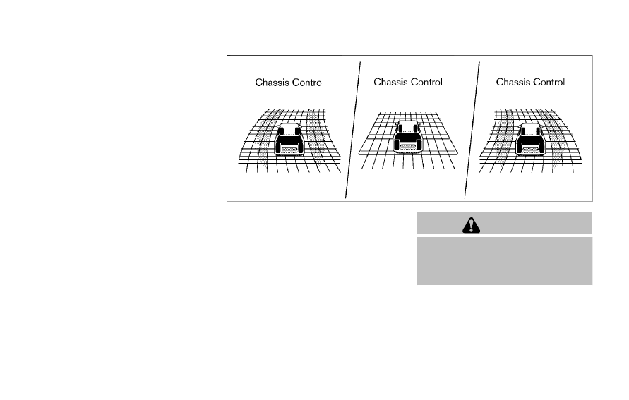
JVS0403X
When the Intelligent Trace Control is
operated and the “Chassis Control” mode
is selected in the trip computer, the
Intelligent Trace Control graphics are
shown in the vehicle information display.
(See “Trip computer” (P.2-34).)
If the chassis control warning message
appears in the vehicle information dis-
play, it may indicate that the Intelligent
Trace Control is not functioning properly.
Have the system checked as soon as
possible. It is recommended that you visit
a NISSAN dealer for this service. (See
“Vehicle information display warnings
and indicators” (P.2-28).)
WARNING
The Intelligent Trace Control may not
be effective depending on the driv-
ing condition. Always drive carefully
and attentively.
When the Intelligent Trace Control is
operating, you may feel a pulsation in
the brake pedal and hear a noise. This is
normal and indicates that the Intelligent
Trace Control is operating properly.
Even if the Intelligent Trace Control is set
to OFF, some functions will remain on to
assist the driver (for example, avoidance
CHASSIS CONTROL