Nissan Qashqai (2007-2010). Manual - part 697


  Index      Nissan     Nissan Qashqai - service and repair manual 2007 - 2010 year


Search            copyright infringement  


Content   ..  695  696  697  698   ..


Nissan Qashqai (2007-2010). Manual - part 697


REAR DISC BRAKE

BR-87

< ON-VEHICLE REPAIR >

[RHD]

C

D

E

G

H

I

J

K

L

M

A

B

BR

N

O

P

BRAKE CALIPER ASSEMBLY : Removal and Installation

INFOID:0000000000938094

REMOVAL

WARNING:

Clean any dust from the brake caliper and brake pads with a vacuum dust collector. Never blow with
compressed air.

CAUTION:

Never depress the brake pedal. Brake fluid may splash while removing the brake hose.
1.

Remove tires.

2.

Fix the disc rotor using wheel nuts.

3.

Drain brake fluid. Refer to 

BR-11, "Draining"

.

CAUTION:

Never spill or splash brake fluid on the disc rotor.

4.

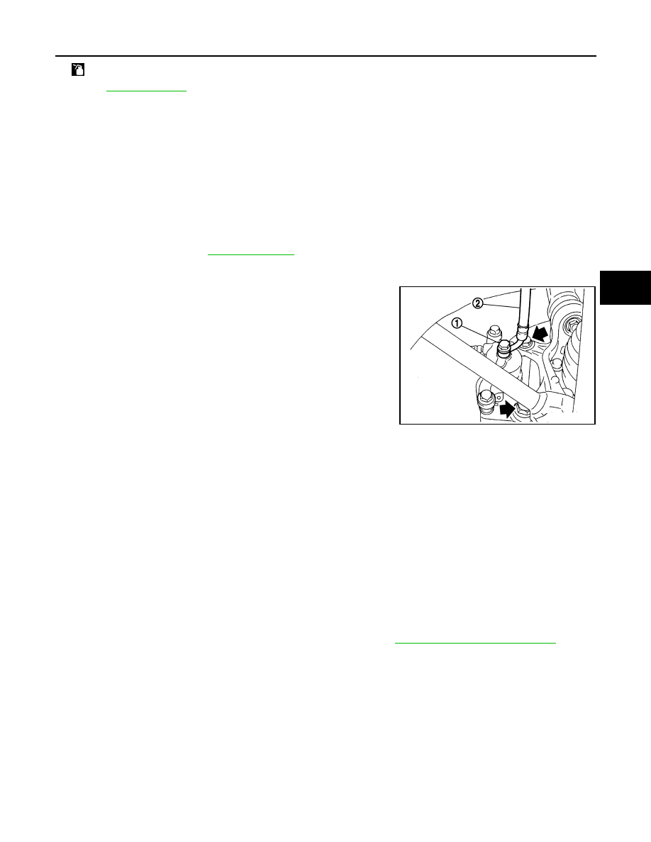
Remove union bolt (1) and then disconnect brake hose (2) from
caliper assembly.

5.

Remove torque member mounting bolts, and remove brake cali-
per assembly.

CAUTION:

Never drop brake pads and caliper assembly.

6.

Remove disc rotor.

CAUTION:

• Put matching marks on the wheel hub and bearing assem-

bly and the disc rotor before removing the disc rotor.

• Never drop disc rotor.

INSTALLATION

WARNING:

Clean any dust from the brake caliper and brake pads with a vacuum dust collector. Never blow with
compressed air.

CAUTION:

Never depress the brake pedal. Brake fluid may splash while removing the brake hose.

1.

Install disc rotor.

CAUTION:

Align the matching marks made during removal when reusing the disc rotor.

2.

Install the brake caliper assembly to the vehicle and tighten the torque member mounting bolts to the
specified torque.

CAUTION:

Never spill or splash any grease and moisture on the brake caliper assembly mounting face,
threads, mounting bolts, and washers. Wipe out any grease and moisture.

3.

Install brake hose to brake caliper assembly, and tighten union bolts to the specified torque.

4.

Refill with new brake fluid and perform the air bleeding. Refer to 

BR-12, "Bleeding Brake System"

.

CAUTION:

• Never reuse drained brake fluid.
• Never spill or splash brake fluid on the disc rotor.

5.

Check that no drag feel is present for the rear disc brake.

6.

Install tires.

BRAKE CALIPER ASSEMBLY : Disassembly and Assembly

INFOID:0000000000938095

DISASSEMBLY

NOTE:
Never remove the torque member, brake pads, shims, shim cover and pad retainers disassembling and
assembling the cylinder body.

: Apply brake fluid.

Refer to 

GI-4, "Components"

 for symbols not described on the above.

JPFIA0036ZZ

BR-88

< ON-VEHICLE REPAIR >

[RHD]

REAR DISC BRAKE

1.

Remove the sliding pin bolts and remove the cylinder body from the torque member.

CAUTION:

Never drop pads, shims, shim cover and pad retainers from torque member.

2.

Remove sliding pin boots from torque member.

3.

Remove bushing from sliding pin bolt.

4.

Place a wooden block as shown in the figure, and blow air from
union bolt mounting hole to remove piston and piston boot.

CAUTION:

Never get fingers caught in the piston.

5.

Remove piston seal from cylinder body using suitable tool.

CAUTION:

Be careful not to damage a cylinder inner wall.

ASSEMBLY

1.

Apply polyglycol ether based lubricant to piston seal (1), and
install to cylinder body.

CAUTION:

Never reuse piston seal.

2.

Apply rubber grease to piston boot (1). Cover the piston (2) end
with the piston boot, and then install cylinder side lip on the pis-
ton boot securely into the groove on cylinder body.

CAUTION:

Never reuse piston boot.

BRD0041D

JPFIA0038ZZ

JPFIA0039ZZ

JPFIA0040ZZ

REAR DISC BRAKE

BR-89

< ON-VEHICLE REPAIR >

[RHD]

C

D

E

G

H

I

J

K

L

M

A

B

BR

N

O

P

3.

Apply brake fluid to piston (1). Push piston into cylinder body by
hand and push piston boot (2) piston side lip into the piston
groove.

CAUTION:

Press the piston evenly and vary the pressing point to pre-
vent cylinder inner wall from being rubbed.

4.

Apply polyglycol ether based lubricant to bushing, install bush-
ing to sliding pin bolt.

5.

Apply rubber grease to the sliding pin bolts and the sliding pin
boots, install sliding pin boot to torque member.

6.

Install the cylinder body to the torque member and tighten the
sliding pin bolts to the specified torque.

BRAKE CALIPER ASSEMBLY : Inspection and Adjustment

INFOID:0000000000938096

INSPECTION AFTER DISASSEMBLY

Cylinder Body

Check the inner wall of the cylinder for rust, wear, cracks or damage. Replace the cylinder if any abnormal
condition is detected.

CAUTION:

Always clean with new brake fluid. Never clean with mineral oil such as gasoline and light oil.

Torque Member

Check the torque member for rust, wear, cracks or damage. Replace the member if any abnormal condition is
detected.

Piston

Check the piston for rust, wear, cracks or damage. Replace the piston if any abnormal condition is detected.

CAUTION:

A piston sliding surface is plated. Never polish with sandpaper.

Sliding Pin Bolt and Sliding Pin Boot

Check the sliding pin bolts and sliding pin boots for rust, wear, cracks or damage. Replace the parts if any
abnormal condition is detected.

ADJUSTMENT AFTER INSTALLATION

Brake Burnishing Procedure

Burnish contact surfaces between disc rotors and pads according to the following procedure after refinishing
or replacing disc rotor, or if a soft pedal occurs at very low mileage.

CAUTION:

• Be careful of vehicle speed because the brake does not operate easily until pad and disc rotor are

securely fitted.

• Only perform this procedure under safe road and traffic conditions. Use extreme caution.

1.

Drive vehicle on straight, flat road.

2.

Depress brake pedal with the power to stop vehicle within 3 to 5 seconds until the vehicle stops.

3.

Drive without depressing brake for a few minutes to cool the brake.

4.

Repeat steps 1 to 3 until pad and disc rotor are securely fitted.

JPFIA0041ZZ

BR-90

< SERVICE DATA AND SPECIFICATIONS (SDS) 

[RHD]

SERVICE DATA AND SPECIFICATIONS (SDS)

SERVICE DATA AND SPECIFICATIONS (SDS)

SERVICE DATA AND SPECIFICATIONS (SDS)

General Specifications

INFOID:0000000000938097

Unit: mm (in.)

Brake Pedal

INFOID:0000000000938098

Unit: mm (in.)

Brake Booster

INFOID:0000000000938099

Vacuum type

Unit: mm (in.)

Front Disc Brake

INFOID:0000000000938100

Unit: mm (in.)

Rear Disc Brake

INFOID:0000000000938101

Unit: mm (in.)

Front brake

Cylinder bore diameter

60.33 (2.375)

Pad length 

×

 width 

×

 thickness

123.6 

×

 47.5 

×

 11.0 (4.87 

×

 1.870 

×

 0.433)

Rotor outer diameter 

×

 thickness

296 

×

 26.0 (11.65 

×

 1.024)

Rear brake 

Cylinder bore diameter

34.93 (1.375)

Pad length 

×

 width 

×

 thickness

83.0 

×

 31.9 

×

 8.5 (3.268 

×

 1.256 

×

 0.335)

Rotor outer diameter 

×

 thickness

292 

×

 9.0 (11.50 

×

 0.354)

Master cylinder

Cylinder bore diameter

23.8 (15/16)

Control valve

Valve type

Electric brake force distribution

Brake booster

Diaphragm diameter

 250 (9.8)

Recommended brake fluid

DOT 4

Brake pedal height (H

1

)

130.2 – 140.2 (5.13 – 5.52)

Clearance (C) between bracket and ASCD cancel switch/stop lamp switch threaded end

0.74 – 1.96 (0.0291 – 0.0772)

Brake pedal play (A)

Depressed brake pedal height (H

2

)

[Depressing 490 N (50 kg, 110 lb) while turning the engine ON]

Output rod length (A)

30.5 (1.201)

Input rod length (B)

124.5 – 125.5 (4.90 – 4.94)

Brake pad

Standard thickness

11.0 (0.433)

Wear limit thickness

2.0 (0.079)

Disc rotor

Standard thickness 

26.0 (1.024)

Wear limit thickness

24.0 (0.945)

Thickness variation (measured at 8 positions)

0.020 (0.0008)

Runout limit (with it attached to the vehicle)

0.035 (0.0014)

Brake pad

Standard thickness 

8.5 (0.335)

Wear limit thickness

2.0 (0.079)


Content   ..  695  696  697  698   ..