Nissan Qashqai (2007-2010). Manual - part 640
ELECTRIC CONTROLLED COUPLING
DLN-133
< DISASSEMBLY AND ASSEMBLY >
[REAR FINAL DRIVE: R145]
C
E
F
G
H
I
J
K
L
M
A
B
DLN
N
O
P
8.
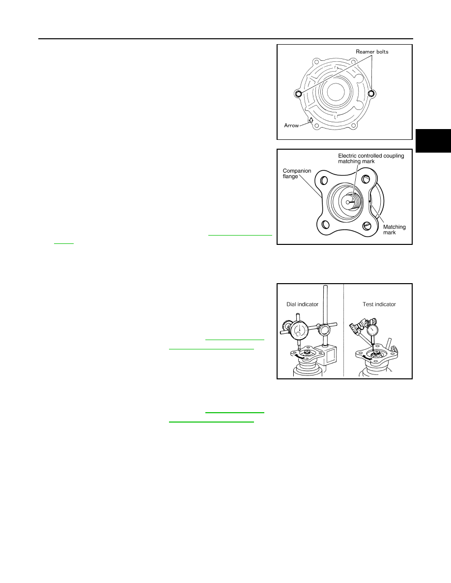
Install coupling cover to gear carrier with arrow facing upward,
temporarily tighten reamer bolts to the positions shown in the
figure.
9.
Tighten reamer bolts and coupling cover mounting bolts to the
specified torque.
10. Install connector bracket, and tighten bolts to the specified
torque.
11. Install companion flange.
NOTE:
When reusing electric controlled coupling, align the matching
mark of electric controlled coupling with the matching mark of
companion flange, then install companion flange.
12. Install companion flange lock nut with flange wrench (commer-
cial service tool), tighten to the specified torque.
CAUTION:
Never reuse companion flange lock nut.
13. Check companion flange runout. Refer to
.
Adjustment
INFOID:0000000000972187
COMPANION FLANGE RUNOUT
1.
Fit a dial indicator onto the companion flange face (inner side of
the rear propeller shaft mounting bolt holes).
2.
Rotate companion flange to check for runout.
3.
Fit a test indicator to the inner side of companion flange (socket
diameter).
4.
Rotate companion flange to check for runout.
5.
If the runout value is outside the runout limit, follow the procedure below to adjust.
a.
Check for runout while changing the phase between companion flange and drive pinion by 90
°
step, and
search for the position where the runout is the minimum.
b.
If the runout value is still outside of the limit after the phase has been changed, replace companion flange.
c.
If the runout value is still outside of the limit after companion flange has been replaced, possible cause will
be an assembly malfunction of drive pinion and electric controlled coupling, malfunctioning coupling bear-
ing, or malfunctioning of electric controlled coupling.
Inspection After Disassembly
INFOID:0000000001077000
Clean up the disassembled parts. Then, inspect if the parts are worn or damaged. If so, follow the measures
below.
SDIA0587E
PDIA0455E
Limit
Companion flange runout
: Refer to
.
Limit
Companion flange runout
: Refer to
.
PDIA0439E