Nissan Qashqai (2007-2010). Manual - part 628


  Index      Nissan     Nissan Qashqai - service and repair manual 2007 - 2010 year


Search            copyright infringement  


Content   ..  626  627  628  629   ..


Nissan Qashqai (2007-2010). Manual - part 628


DRIVE PINION

DLN-85

< DISASSEMBLY AND ASSEMBLY >

[TRANSFER: TY30A]

C

E

F

G

H

I

J

K

L

M

A

B

DLN

N

O

P

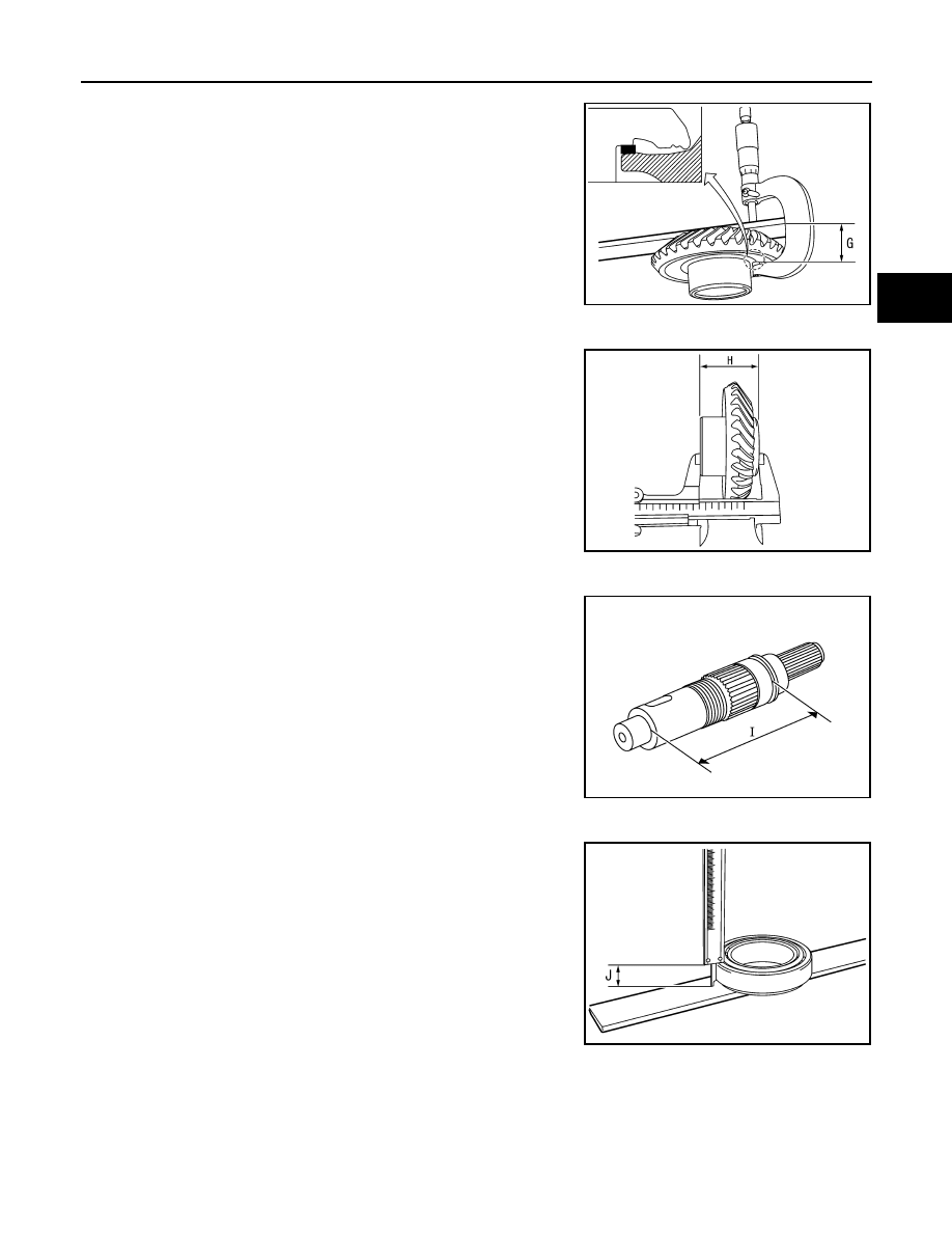
Dimension “G” measurement

• Measure dimension from ring gear shaft bearing mounting sur-

face of ring gear to transfer case side edge surface with a
micrometer and straightedge. Refer to “Measuring point”.

CAUTION:

Consider the thickness of a straightedge.

Dimension “H” measurement

• Measure dimension from transfer case side edge surface of

ring gear to adapter case side edge surface with a pair of ver-
nier calipers. Refer to “Measuring point”.

Dimension “I” measurement

• Measure dimension from ring gear mounting surface of ring

gear shaft to ring gear shaft bearing (transfer case side)
mounting surface with a pair of vernier calipers. Refer to “Mea-
suring point”.

Dimension “J” measurement

• Measure dimension from outer race edge surface of ring gear

shaft bearing (transfer case side) to inner race edge surface
with a pair of vernier calipers. Refer to “Measuring point”.

2.

Calculate dimension “N” by the formula below.

3.

Convert the dimensions “F”, “G”, “H”, “I”, “J” and “N” according to the standards below.

SDIA3111J

SDIA3112J

JSDIA0257ZZ

SDIA3128J

Dimension “N” = “C” 

×

 0.5 mm (0.020 in) + “D”

DLN-86

< DISASSEMBLY AND ASSEMBLY >

[TRANSFER: TY30A]

DRIVE PINION

4.

Check dimension “Z” (machining difference) on the ring gear
back surface.
NOTE:
Dimension “Z” indicates difference between optimum engage-
ment and the standard dimensions in increments of 0.01 mm
(0.0004 in) written on the ring gear back surface.

5.

Calculate the thickness of the ring gear adjusting shim (transfer
case side) “T

2

” by the formula below.

6.

Select ring gear adjusting shim (transfer case side).

CAUTION:

• Only one adjusting shim can be selected.
• Select the closest one, favoring thicker over thinner when necessary if no adjusting shim with

the calculated value is available.

Drive Pinion Adjusting Shim

1.

Check the dimension “U” (machining difference) between old
and new drive pinions when hypoid gear set (drive pinion and
ring gear) has been replaced.
(Assemble new drive pinion adjusting shims with the same thick-
ness as the ones removed prior to disassembly or removed
drive pinion adjusting shims when reusing the hypoid gear set.)
NOTE:
Dimension “U” indicates the difference between optimum
engagement and the standard dimensions in increments of 0.01
mm (0.0004 in). It is written on the gear end of the drive pinion
for reference.

2.

Calculate the thickness of the drive pinion adjusting shim “T” by
the formula below.

3.

Select drive pinion adjusting shim.

“F”

: Actual value regarding 122.60 mm (4.83 in) as 0 in increments of 0.01 mm (0.0004 in).

“G”

: Actual value regarding 26.60 mm (1.0472 in) as 0 in increments of 0.01 mm (0.0004 in).

“H”

: Actual value regarding 48.60 mm (1.9134 in) as 0 in increments of 0.01 mm (0.0004 in).

“I”

: Actual value regarding 119.40 mm (4.70 in) as 0 in increments of 0.01 mm (0.0004 in).

“J”

: Actual value regarding 16.25 mm (0.6398 in) as 0 in increments of 0.01 mm (0.0004 in).

“N”

: Actual value regarding 55.00 mm (2.1654 in) as 0 in increments of 0.01 mm (0.0004 in).

“T

2

” = (“F” – “G” + “H” – “I” – “J” – “N” + “Z”) 

×

 0.01 mm 

(0.0004 in) + 1.65 mm (0.0650 in)

SDIA3129J

“T” = T

0

 + [(t

1

 – t

2

×

 0.01 mm (0.0004 in)]

“T”

: Thickness of new shim

T

0

: Thickness of old shim

t

1

: Dimension “U” displayed on the gear end of 
old drive pinion

t

2

: Dimension “U” displayed on the gear end of 
new drive pinion

[Example]

“T” = 3.21 + [(2 + 1) 

×

 0.01 mm (0.0004 in)]

T

0

: 3.21

t

1

: +2

t

2

1

SDIA3131J

DRIVE PINION

DLN-87

< DISASSEMBLY AND ASSEMBLY >

[TRANSFER: TY30A]

C

E

F

G

H

I

J

K

L

M

A

B

DLN

N

O

P

CAUTION:

• Only one adjusting shim can be selected.
• Select the closest one, if no adjusting shim with the calculated value is available.

M/T : Inspection After Disassembly

INFOID:0000000000972148

Check items below. If necessary, replace them with new ones.

GEAR AND SHAFT

Check gear face and shaft for wear, cracks, damage, and seizure.

CAUTION:

Replace ring gear and drive pinion as a set (hypoid gear set) if any malfunction is detected on the ring
gear or drive pinion.

BEARING

Check for seizure, peeling, wear, corrosion, sticking, unusual noise, roughness in hand turning, and other
damage.

CAUTION:

Always replace inner race and outer race as a pair when replacing the bearing.

SHIM

Check for seizure, damage, and unusual wear.

CASE

Check the bearing mounting surface for wear, cracks and damages.

CVT

CVT : Exploded View

INFOID:0000000001060138

DLN-88

< DISASSEMBLY AND ASSEMBLY >

[TRANSFER: TY30A]

DRIVE PINION

CVT : Disassembly

INFOID:0000000001060153

1.

Adapter case oil seal

2.

Adapter case

3.

O-ring

4.

Ring gear shaft

5.

Ring gear adjusting shim
(adapter case side)

6.

Ring gear shaft bearing
(adapter case side)

7.

Ring gear

8.

Ring gear nut

9.

Ring gear shaft bearing
(transfer case side)

10. Ring gear adjusting shim

(transfer case side)

11.

Transfer case

12. Air breather hose

13. Air breather tube

14. Gasket

15. Filler plug

16. Drain plug

17. Plug

18. Drive pinion

19. Drive pinion adjusting shim

20. Drive pinion bearing (front side)

21. Collapsible spacer

22. Drive pinion bearing (rear side)

23. Drive pinion oil seal

24. Companion flange

25. Lock nut

A: Oil seal lip

: Apply gear oil.

: Apply anti-corrosive oil.

: Apply Genuine Liquid Gasket, Three Bond TB1215 or equivalent.

Refer to 

GI-4, "Components"

 for symbols not described on the above.

JSDIA0211GB


Content   ..  626  627  628  629   ..