Nissan Qashqai (2007-2010). Manual - part 615
4WD CONTROL UNIT
DLN-33
< ECU DIAGNOSIS >
[TRANSFER: TY30A]
C
E
F
G
H
I
J
K
L
M
A
B
DLN
N
O
P
*: The values are changed by throttle opening and engine speed.
CAUTION:
When using circuit tester to measure voltage for inspection, be sure not to extend forcibly any connector terminals.
Wiring Diagram - 4WD SYSTEM -
INFOID:0000000000972104
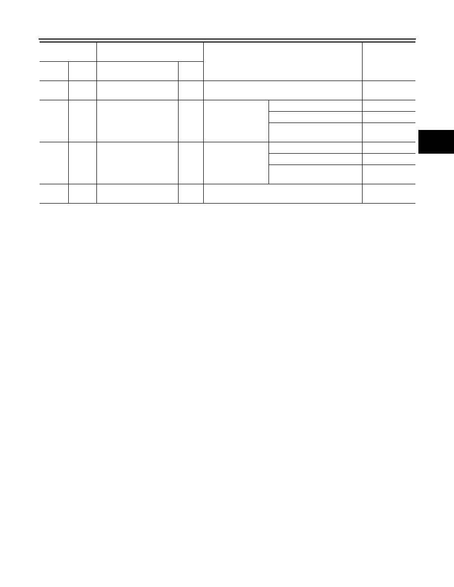
11
(B)
Ground
Ground
—
Always
0 V
12
(BR)
Ground
4WD mode switch (2WD)
Output
Ignition switch: ON
4WD mode switch: 2WD
0 V
4WD mode switch: AUTO
Battery voltage
4WD mode switch: LOCK
(State of hold of LOCK position)
Battery voltage
14
(Y)
Ground
4WD mode switch (LOCK)
Output
Ignition switch: ON
4WD mode switch: 2WD
Battery voltage
4WD mode switch: AUTO
Battery voltage
4WD mode switch: LOCK
(State of hold of LOCK position)
0 V
16
(P)
Ground
CAN-L
—
—
—
Terminal No.
(Wire color)
Description
Condition
Value (Approx.)
+
-
Signal name
Input/
Output