Nissan Qashqai (2007-2010). Manual - part 602
DIFFERENTIAL SIDE OIL SEAL
TM-343
< ON-VEHICLE REPAIR >
[CVT: RE0F10A]
C
E
F
G
H
I
J
K
L
M
A
B
TM
N
O
P
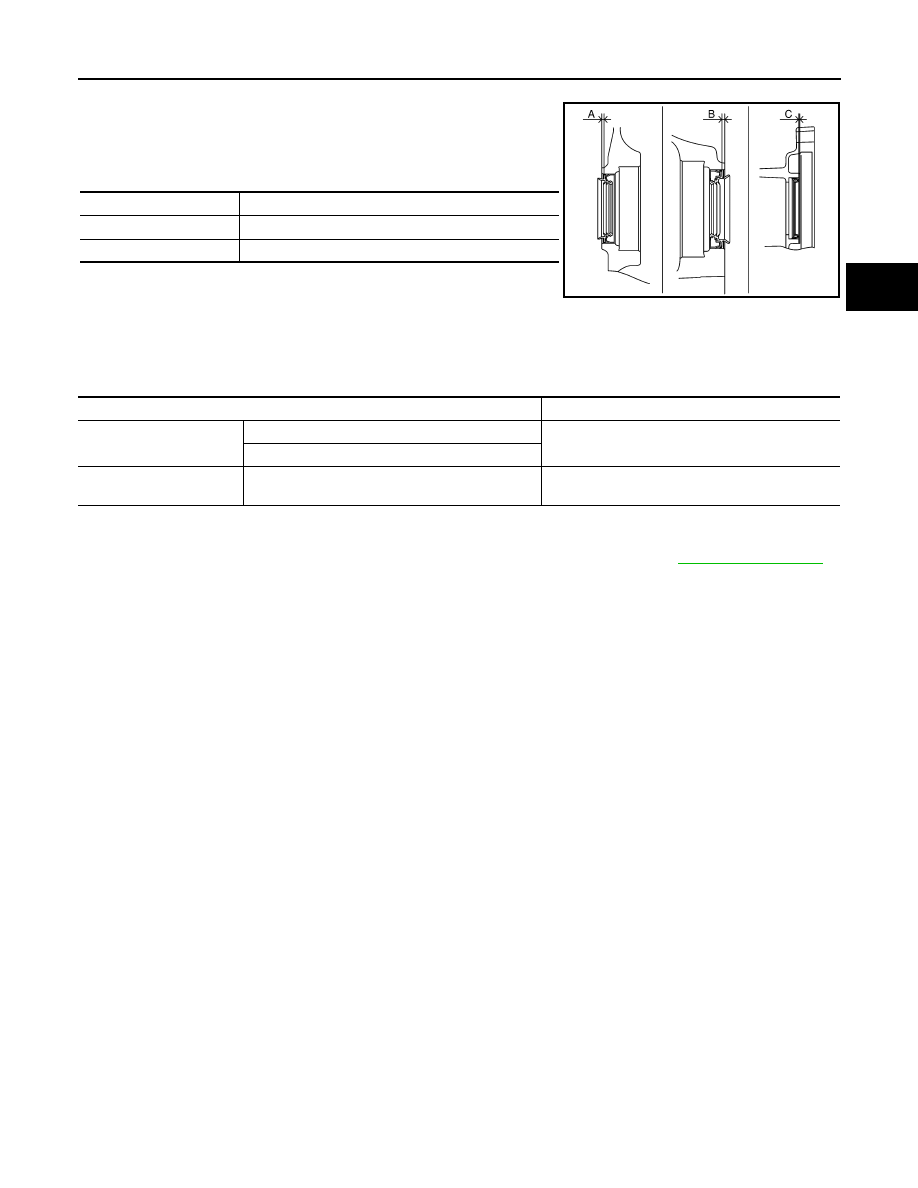
Note the following, and install in the reverse order of removal.
• Drive each differential side oil seal and side oil seal (transfer joint)
evenly using a commercial service tool so that differential side oil
seal and side oil seal (transfer joint) protrudes by the dimension
(A), (B), or (C) respectively.
Unit: mm (in)
NOTE:
Differential side oil seal and side oil seal (transfer joint) pulling direc-
tion is used as the reference.
CAUTION:
• Never reuse differential side oil seals and side oil seal (transfer joint).
• Apply CVT fluid to differential side oil seals and side oil seal (transfer joint).
Drift to be used:
4WD : Inspection
INFOID:0000000001091252
After completing installation, check for CVT fluid leakage and CVT fluid level. Refer to
.
Dimension A
1.8
±
0.5 (0.071
±
0.020)
Dimension B
2.2
±
0.5 (0.087
±
0.020)
Dimension C
0.5
±
0.5 (0.020
±
0.020)
SCIA6609J
Location
Tool number
Differential side oil seal
Transaxle case side
Commercial service tool [Outer diameter: 54 mm
(2.13 in), inner diameter: 47 mm (1.85 in)]
Converter housing side
Side oil seal (transfer joint)
Transaxle engagement
Commercial service tool [Outer diameter: 70 mm
(2.76 in), inner diameter: 56 mm (2.20 in)]