Nissan Qashqai (2007-2010). Manual - part 538


  Index      Nissan     Nissan Qashqai - service and repair manual 2007 - 2010 year


Search            copyright infringement  


Content   ..  536  537  538  539   ..


Nissan Qashqai (2007-2010). Manual - part 538


TRANSAXLE ASSEMBLY

TM-87

< DISASSEMBLY AND ASSEMBLY >

[6MT: RS6F94R]

C

E

F

G

H

I

J

K

L

M

A

B

TM

N

O

P

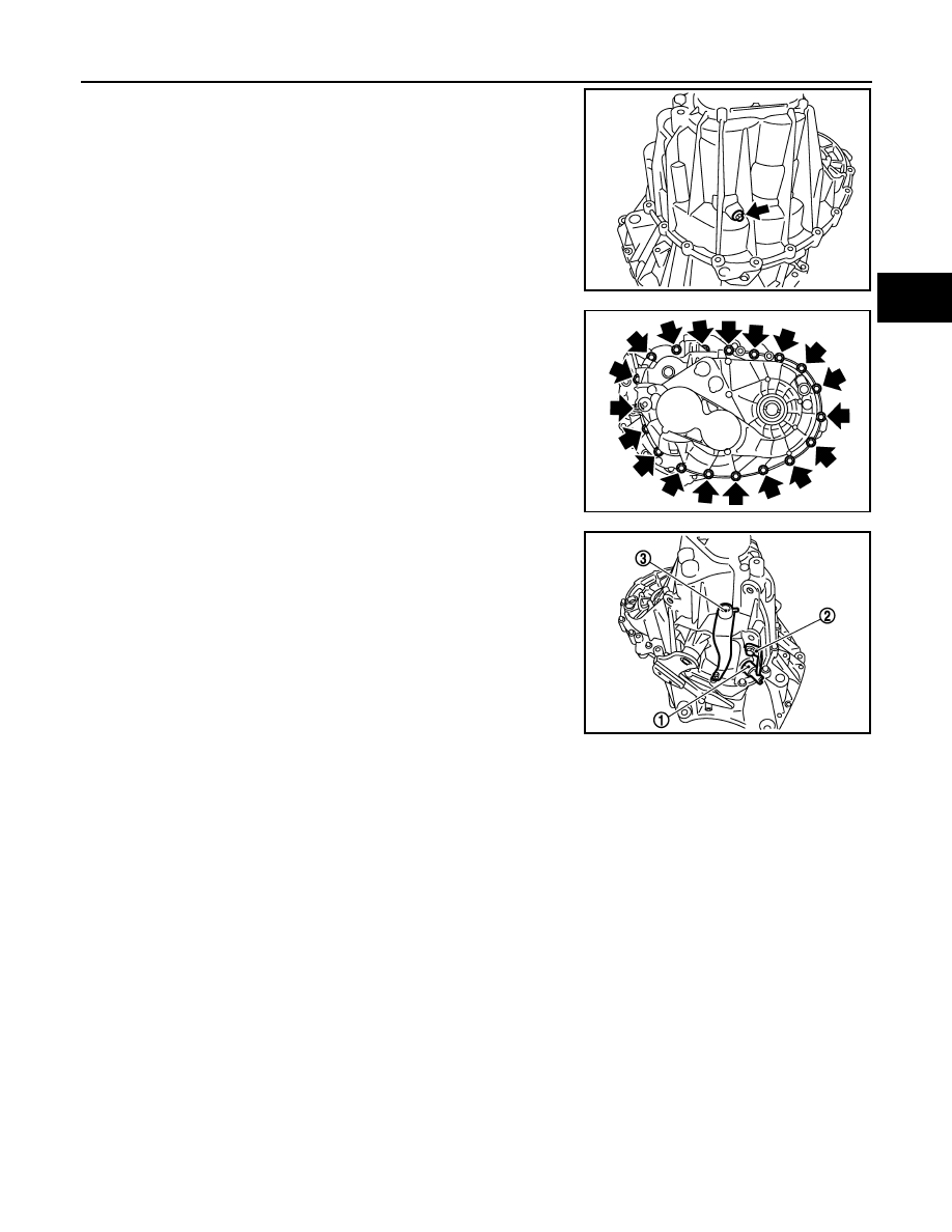
30. Install seal washer and reverse idler shaft mounting bolt, and

then tighten mounting bolt to the specified torque.

CAUTION:

Never reuse seal washer.

31. Tighten mounting bolts to the specified torque.

32. Apply recommended sealant to threads of position switch (1).

Then install it to transaxle case and tighten to the specified
torque.
• Use Genuine Liquid Gasket, Three Bond 1215 or an equiv-

alent.

33. Install bracket (2), and then mounting bolt to the specified

torque.

34. Install shifter lever (3), and then install retaining pin using a pin

punch.

CAUTION:

Never reuse retaining pin.

35. Install gasket onto drain plug, and then install it into clutch hous-

ing using the socket [Commercial service tool]. Tighten drain plug to the specified torque.

CAUTION:

Never reuse gasket.

36. Install gasket onto filler plug, and then install it into transaxle case. Tighten filler plug to the specified

torque.

CAUTION:

• Never reuse gasket.
• After gear oil is filled, tighten filler plug to specified torque.

PCIB1695E

PCIB1694E

SCIA7784E

TM-88

< DISASSEMBLY AND ASSEMBLY >

[6MT: RS6F94R]

INPUT SHAFT AND GEAR

INPUT SHAFT AND GEAR

Exploded View

INFOID:0000000001070341

Refer to 

TM-71, "Exploded View"

.

Disassembly

INFOID:0000000001070342

CAUTION:

• Set input shaft on the vise with back plate and remove gears and snap rings.
• For installation and removal of snap ring, set snap ring pliers

and flat pliers at both sides of snap ring. Stretch snap ring,
and move it with flat pliers.

• Disassemble gear components putting matching marks on

the parts that do not affect any functions.

1.

Remove snap ring (1).

2.

Set the drift (A) [Commercial service tool] and puller to input
shaft rear bearing (1), and remove input shaft rear bearing from
input shaft using a press.

3.

Remove washer (1), 6th input gear (2) and 5th-6th synchronizer
assembly (3).

4.

Remove needle bearing.

SCIA1755J

PCIB1756E

JPDIC0111ZZ

PCIB1750E

INPUT SHAFT AND GEAR

TM-89

< DISASSEMBLY AND ASSEMBLY >

[6MT: RS6F94R]

C

E

F

G

H

I

J

K

L

M

A

B

TM

N

O

P

5.

Remove snap ring (1), washer and 5th input gear (2). 

6.

Remove washer.

7.

Remove snap ring (1), washer, 4th input gear (2) and 3rd-4th
synchronizer assembly (3).

8.

Remove snap ring (1), washer and 3rd input gear (2).

9.

Remove input shaft front bearing (1) from input shaft using a
press.

Assembly

INFOID:0000000001070343

Note the following, and assembly is in the reverse order of disassembly.

PCIB1754E

PCIB1753E

PCIB1752E

PCIB1751E

TM-90

< DISASSEMBLY AND ASSEMBLY >

[6MT: RS6F94R]

INPUT SHAFT AND GEAR

• Press-fit the input shaft front bearing (1) onto the input shaft using

the drift (A) [Commercial service tool] and press.

• Press-fit the input shaft rear bearing (1) onto the input shaft using

the drift (A) [Commercial service tool], the drift (B) [SST:
ST36720030] and press.

CAUTION:

• Never reuse snap ring.
• Make sure that snap ring is securely installed in the groove.
• Apply gear oil to baulk ring.
• Replace coupling sleeve and synchronizer hub as a set.
• Be careful with the orientation of 3rd-4th synchronizer hub.

• Be careful with the orientation of 5th-6th synchronizer hub.

Inspection

INFOID:0000000001070344

INPUT SHAFT AND GEAR

JPDIC0112ZZ

JPDIC0113ZZ

A

: 3rd input gear side

B

: 4th input gear side

PCIB1748E

A

: 5th input gear side

B

: 6th input gear side

PCIB1749E


Content   ..  536  537  538  539   ..