Nissan Qashqai (2007-2010). Manual - part 498
FL-28
< ON-VEHICLE REPAIR >
[K9K]
FUEL TANK
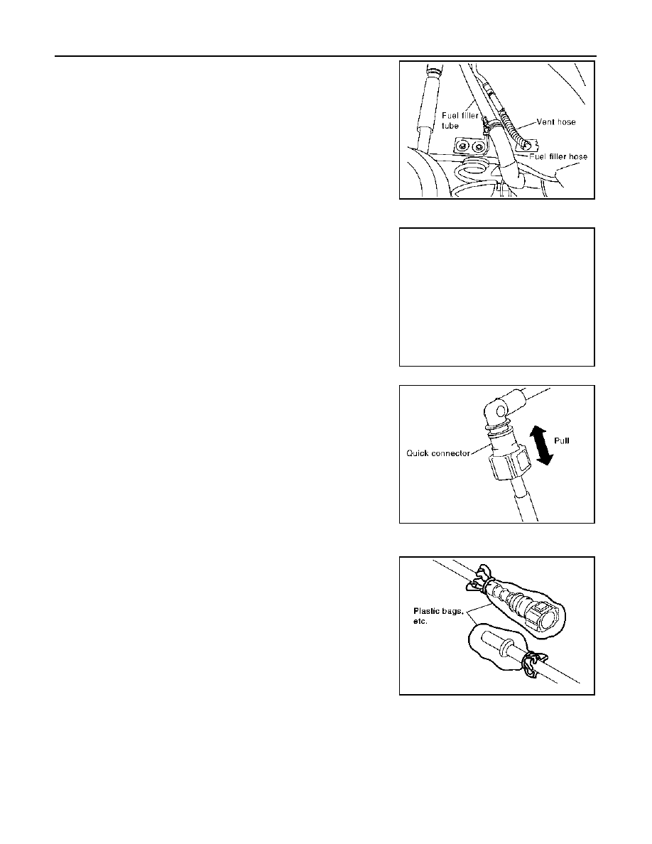
6.
Disconnect fuel filler hose on fuel tank side.
CAUTION:
Do not remove fuel filler hose at fuel filler tube side, pre-
venting to interfere with suspension due to dislocation
when installing. When removing at fuel filler tube side nec-
essarily, put mating marks, and remove.
7.
Remove vent hose at RH rear wheelwell side.
8.
Remove EVAP hose at front side of fuel tank.
• Remove quick connector in the following procedures.
- Pinch quick connector square-parts with your fingers, and pull
out the quick connector by hand.
- If quick connector and tube on vehicle are stuck, push and pull
several times until they move, and pull out.
CAUTION:
• The tube can be removed when the tabs are completely
depressed. Do not twist it more than necessary.
• Do not use any tools to remove the quick connector.
• Keep the resin tube away from heat. Be especially care-
ful when welding near the tube.
• Prevent acid liquid such as battery electrolyte etc. from
getting on the resin tube.
• Do not bend or twist the tube during installation and removal.
• To keep clean the connecting portion and to avoid damage
and foreign materials, cover them completely with plastic bags
or something similar.
CAUTION:
Do not insert plug, preventing damage on O-ring in quick
connector.
PBIC1505E
PBIC1507E
PBIC1509E
PBIC0713E