Nissan Qashqai (2007-2010). Manual - part 387


  Index      Nissan     Nissan Qashqai - service and repair manual 2007 - 2010 year


Search            copyright infringement  


Content   ..  385  386  387  388   ..


Nissan Qashqai (2007-2010). Manual - part 387


POWER SUPPLY AND GROUND CIRCUIT

EC-1067

< COMPONENT DIAGNOSIS >

[MR20DE (WITHOUT EURO-OBD)]

C

D

E

F

G

H

I

J

K

L

M

A

EC

N

P

O

>> Repair open circuit or short to power in harness or connectors.

7.

CHECK ECM POWER SUPPLY CIRCUIT-II

1.

Reconnect ECM harness connectors.

2.

Turn ignition switch ON.

3.

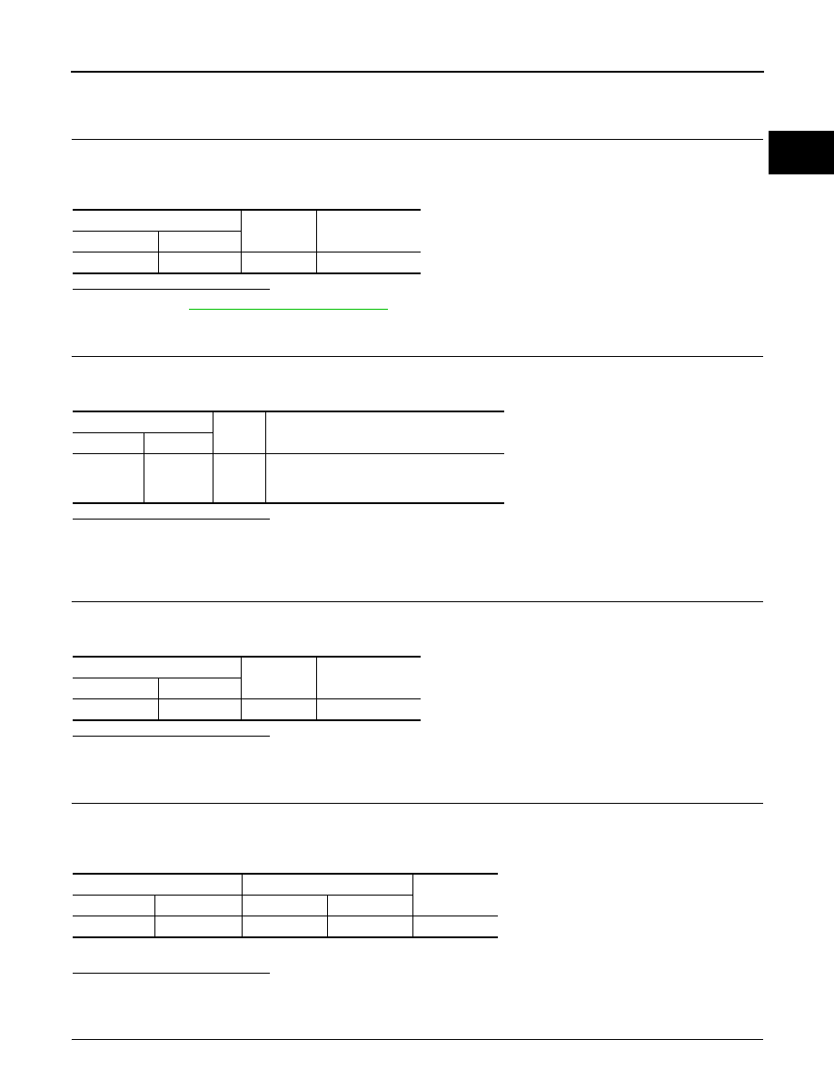
Check the voltage between IPDM E/R harness connector and ground.

Is the inspection result normal?

YES

>> Go to 

EC-929, "Diagnosis Procedure"

.

NO

>> GO TO 8.

8.

CHECK ECM POWER SUPPLY CIRCUIT-III

1.

Turn ignition switch OFF and wait at least 10 seconds.

2.

Check the voltage between ECM harness connector and ground.

Is the inspection result normal?

YES

>> GO TO 14.

NO-1

>> Battery voltage does not exist: GO TO 9.

NO-2

>> Battery voltage exists for more than a few seconds: GO TO 12.

9.

CHECK ECM POWER SUPPLY CIRCUIT-IV

1.

Turn ignition switch OFF and wait at least 10 seconds.

2.

Check the voltage between ECM harness connector and ground.

Is the inspection result normal?

YES

>> GO TO 10.

NO

>> GO TO 11.

10.

CHECK ECM POWER SUPPLY CIRCUIT-V

1.

Disconnect ECM harness connector.

2.

Disconnect IPDM E/R harness connector.

3.

Check the continuity between ECM harness connector and IPDM E/R harness connector.

4.

Also check harness for short to ground and short to power.

Is the inspection result normal?

YES

>> GO TO 13.

NO

>> Repair open circuit or short to ground or short power in harness or connectors.

11.

CHECK ECM POWER SUPPLY CIRCUIT-VI

IPDM E/R

Ground

Voltage

Connector

Terminal

E11

10

Ground

Battery voltage

ECM

Ground

Voltage

Connector

Terminal

E16

105

Ground

After turning ignition switch OFF, battery volt-
age will exist for a few seconds, then drop ap-
proximately 0V.

ECM

Ground

Voltage

Connector

Terminal

F7

32

Ground

Battery voltage

ECM

IPDM E/R

Continuity

Connector

Terminal

Connector

Terminal

E16

105

E11

9

Existed

EC-1068

< COMPONENT DIAGNOSIS >

[MR20DE (WITHOUT EURO-OBD)]

POWER SUPPLY AND GROUND CIRCUIT

1.

Disconnect ECM harness connector.

2.

Disconnect IPDM E/R harness connector E11.

3.

Check the continuity between ECM harness connector and IPDM E/R harness connector.

4.

Also check harness for short to ground and short to power.

Is the inspection result normal?

YES

>> GO TO 13.

NO

>> GO TO 12.

12.

DETECT MALFUNCTIONING PART

Check the following.
• Junction block connectors E6, F123
• Harness for open or short between ECM and IPDM E/R

>> Repair open circuit or short to ground or short to power in harness or connectors.

13.

CHECK 20A FUSE

1.

Disconnect 20A fuse (No. 62) from IPDM E/R.

2.

Check 20A fuse.

Is the inspection result normal?

YES

>> GO TO 17.

NO

>> Replace 20A fuse.

14.

CHECK GROUND CONNECTION-II

1.

Turn ignition switch OFF.

2.

Check ground connection E21. Refer to Ground Inspection in 

GI-41, "Circuit Inspection"

.

Is the inspection result normal?

YES

>> GO TO 15.

NO

>> Repair or replace ground connection.

15.

CHECK ECM GROUND CIRCUIT FOR OPEN AND SHORT-II

1.

Disconnect ECM harness connector.

2.

Check the continuity between ECM harness connector and ground.

3.

Also check harness for short to power.

Is the inspection result normal?

YES

>> GO TO 17.

NO

>> GO TO 16.

16.

DETECT MALFUNCTIONING PART

Check the following.
• Harness or connectors F121, E7
• Harness for open or short between ECM and ground

>> Repair open circuit or short to power in harness or connectors.

ECM

IPDM E/R

Continuity

Connector

Terminal

Connector

Terminal

F7

32

E11

15

Existed

ECM

Ground

Continuity

Connector

Terminal

F7

10

Ground

Existed

11

E16

108

POWER SUPPLY AND GROUND CIRCUIT

EC-1069

< COMPONENT DIAGNOSIS >

[MR20DE (WITHOUT EURO-OBD)]

C

D

E

F

G

H

I

J

K

L

M

A

EC

N

P

O

17.

CHECK INTERMITTENT INCIDENT

Refer to 

GI-39, "Intermittent Incident"

.

Is the inspection result normal?

YES

>> Replace IPDM E/R.

NO

>> Repair open circuit or short to power in harness or connectors.

EC-1070

< COMPONENT DIAGNOSIS >

[MR20DE (WITHOUT EURO-OBD)]

U1001 CAN COMM CIRCUIT

U1001 CAN COMM CIRCUIT

Description

INFOID:0000000001094089

CAN (Controller Area Network) is a serial communication line for real time application. It is an on-vehicle mul-
tiplex communication line with high data communication speed and excellent error detection ability. Many elec-
tronic control units are equipped onto a vehicle, and each control unit shares information and links with other
control units during operation (not independent). In CAN communication, control units are connected with 2
communication lines (CAN H line, CAN L line) allowing a high rate of information transmission with less wiring.
Each control unit transmits/receives data but selectively reads required data only.

DTC Logic

INFOID:0000000001094090

DTC DETECTION LOGIC

DTC CONFIRMATION PROCEDURE

1.

PERFORM DTC CONFIRMATION PROCEDURE

1.

Turn ignition switch ON and wait at least 3 seconds.

2.

Check DTC.

Is DTC detected?

YES

>>

EC-1073, "Diagnosis Procedure"

.

NO

>> INSPECTION END

Diagnosis Procedure

INFOID:0000000001094091

Go to 

LAN-46, "Trouble Diagnosis Flow Chart"

.

DTC No.

Trouble diagnosis 

name

DTC detecting condition

Possible cause

U1001

CAN communication 
line

When ECM is not transmitting or receiving CAN com-
munication signal other than OBD (emission related 
diagnosis) for 2 seconds or more.

• Harness or connectors

(CAN communication line is open or 
shorted)


Content   ..  385  386  387  388   ..