Nissan Qashqai (2007-2010). Manual - part 383
ON BOARD DIAGNOSTIC (OBD) SYSTEM
EC-1051
< FUNCTION DIAGNOSIS >
[MR20DE (WITHOUT EURO-OBD)]
C
D
E
F
G
H
I
J
K
L
M
A
EC
N
P
O
• Freeze frame data
• 1st trip freeze frame data
• Test values
How to Switch Diagnostic Test Mode
NOTE:
• It is better to count the time accurately with a clock.
• It is impossible to switch the diagnostic mode when an accelerator pedal position sensor circuit has
a malfunction.
• Always ECM returns to Diagnostic Test Mode I after ignition switch is turned OFF.
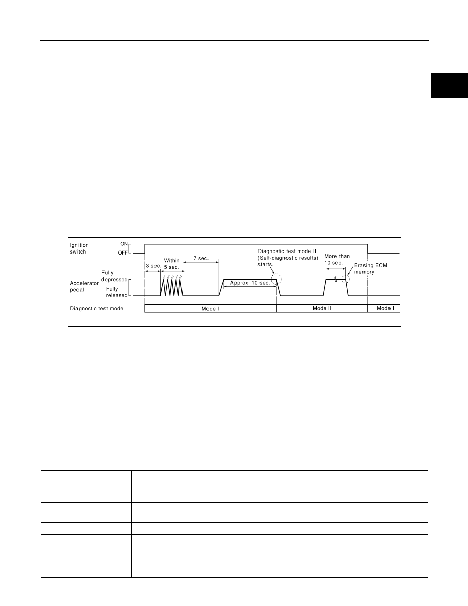
HOW to SET DIAGNOSTIC TEST MODE II (SELF-DIAGNOSTIC RESULTS)
1.
Confirm that accelerator pedal is fully released, turn ignition switch ON and wait 3 seconds.
2.
Repeat the following procedure quickly five times within 5 seconds.
a.
Fully depress the accelerator pedal.
b.
Fully release the accelerator pedal.
3.
Wait 7 seconds, fully depress the accelerator pedal and keep it for approx. 10 seconds until the MI starts
blinking.
4.
Fully release the accelerator pedal.
ECM has entered to Diagnostic Test Mode II (Self-diagnostic results).
NOTE:
Wait until the same DTC (or 1st trip DTC) appears to confirm all DTCs certainly.
HOW to SET DIAGNOSTIC TEST MODE II (HEATED OXYGEN SENSOR 1 MONITOR)
1.
Set the ECM in Diagnostic Test Mode II (Self-diagnostic results).
Refer to “HOW to SET DIAGNOSTIC TEST MODE II (SELF-DIAGNOSTIC RESULTS)”.
2.
Start Engine.
ECM has entered to Diagnostic Test Mode II (Heated oxygen sensor 1 monitor).
HOW to ERASE DIAGNOSTIC TEST MODE II (SELF-DIAGNOSTIC RESULTS)
1.
Set ECM in Diagnostic Test Mode II (Self-diagnostic results). Refer to “HOW to SET DIAGNOSTIC TEST
MODE II (SELF-DIAGNOSTIC RESULTS)”.
2.
Fully depress the accelerator pedal and keep it for more than 10 seconds.
The emission-related diagnostic information has been erased from the backup memory in the ECM.
3.
Fully release the accelerator pedal, and confirm the DTC 0000 is displayed.
CONSULT-III Function
INFOID:0000000001094083
FUNCTION
PBIB0092E
Diagnostic test mode
Function
Work support
This mode enables a technician to adjust some devices faster and more accurately by following the in-
dications on the CONSULT-III unit.
Self-diagnostic results
Self-diagnostic results such as 1st trip DTC, DTCs and 1st trip freeze frame data or freeze frame data
can be read and erased quickly.*
Data monitor
Input/Output data in the ECM can be read.
Active test
Diagnostic Test Mode in which CONSULT-III drives some actuators apart from the ECMs and also shifts
some parameters in a specified range.
Function test
This mode is used to inform customers when their vehicle condition requires periodic maintenance.
ECU part number
ECM part number can be read.