Nissan Qashqai (2007-2010). Manual - part 340
P1564 ASCD STEERING SWITCH
EC-879
< COMPONENT DIAGNOSIS >
[MR20DE (WITH EURO-OBD)]
C
D
E
F
G
H
I
J
K
L
M
A
EC
N
P
O
1.
Check the continuity between ECM harness connector and ASCD steering switch.
2.
Also check harness for short to ground and short to power.
Is the inspection result normal?
YES
>> GO TO 7.
NO
>> GO TO 6.
6.
DETECT MALFUNCTIONING PART
Check the following.
• Harness connectors M77, E105
• Combination switch (spiral cable)
• Harness for open and short between ECM and ASCE steering switch
>> Repair open circuit or short to ground or short to power in harness or connectors.
7.
CHECK ASCD STEERING SWITCH
EC-882, "Component Inspection"
Is the inspection result normal?
YES
>> GO TO 8.
NO
>> Replace ASCD steering switch.
8.
CHECK INTERMITTENT INCIDENT
GI-39, "Intermittent Incident"
.
>> INSPECTION END
Component Inspection
INFOID:0000000001089466
1.
CHECK ASCD STEERING SWITCH
1.
Disconnect combination switch (spiral cable) harness connector.
2.
Check the continuity between combination switch harness connector terminals under following conditions.
Is the inspection result normal?
YES
>> INSPECTION END
NO
>> Replace ASCD steering switch
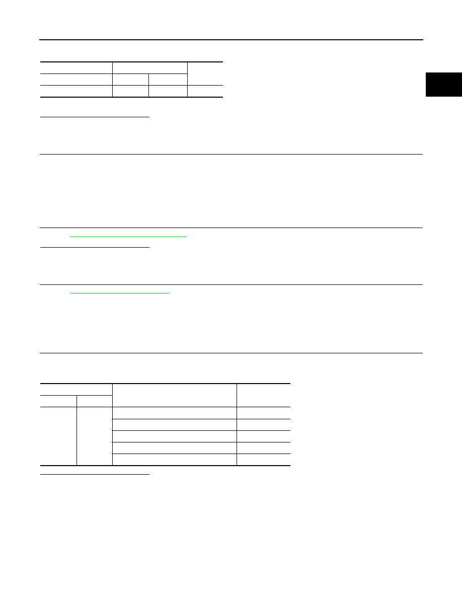
ASCD steering switch
ECM
Continuity
Terminal
Connector
Terminal
14
E16
94
Existed
Combination meter
Condition
Resistance
Connector
Terminals
M325
14 and 15
MAIN switch: Pressed
Approx. 0
Ω
CANCEL switch: Pressed
Approx. 250
Ω
SET/COAST switch: Pressed
Approx. 660
Ω
RESUME/ACCELERATE switch: Pressed
Approx. 1,480
Ω
All ASCD steering switches: Released
Approx. 4,000
Ω