Nissan Qashqai (2007-2010). Manual - part 191
P2127, P2128 APP SENSOR
EC-283
< COMPONENT DIAGNOSIS >
[HR16DE (WITH EURO-OBD)]
C
D
E
F
G
H
I
J
K
L
M
A
EC
N
P
O
NO
>> Repair or replace ground connection.
2.
CHECK APP SENSOR 2 POWER SUPPLY CIRCUIT-I
1.
Disconnect accelerator pedal position (APP) sensor harness connector.
2.
Turn ignition switch ON.
3.
Check the voltage between APP sensor harness connector and ground.
Is the inspection result normal?
YES
>> GO TO 6.
NO
>> GO TO 3.
3.
CHECK APP SENSOR 2 POWER SUPPLY CIRCUIT-II
1.
Turn ignition switch OFF.
2.
Disconnect ECM harness connector.
3.
Check the continuity between APP sensor harness connector and ECM harness connector.
Is the inspection result normal?
YES
>> GO TO 4.
NO
>> Repair open circuit or short to ground or short to power in harness or connectors.
4.
CHECK APP SENSOR 2 POWER SUPPLY CIRCUIT-III
Check harness for short to power and short to ground, between the following terminals.
Is the inspection result normal?
YES
>> GO TO 5.
NO
>> Repair short to ground or short to power in harness or connectors.
5.
CHECK COMPONENTS
Check the following.
• Crankshaft position sensor (POS) (Refer to
EC-196, "Component Inspection"
• Refrigerant pressure sensor (Refer to
HAC-70, "Component Inspection"
.)
Is the inspection result normal?
YES
>> GO TO 10.
NO
>> Replace malfunctioning component.
6.
CHECK APP SENSOR 2 GROUND CIRCUIT FOR OPEN AND SHORT
1.
Turn ignition switch OFF.
2.
Disconnect ECM harness connector.
3.
Check the continuity between APP sensor harness connector and ECM harness connector.
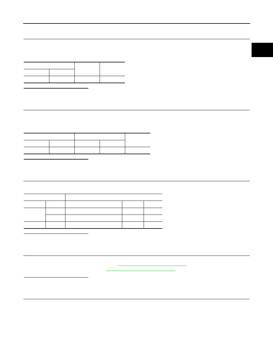
APP sensor
Ground
Voltage
Connector
Terminal
E110
5
Ground
Approx. 5V
APP sensor
ECM
Continuity
Connector
Terminal
Connector
Terminal
E110
5
E16
102
Existed
ECM
Sensor
Connector
Terminal
Item
Connector
Terminal
F8
74
Refrigerant pressure sensor
E49
3
75
CKP sensor (POS)
F20
1
E16
102
APP sensor
E110
5