Content .. 1853 1854 1855 1856 ..
Nissan Qashqai (2007-2010). Manual - part 1855
PCS-24
< ECU DIAGNOSIS >
[IPDM E/R]
IPDM E/R (INTELLIGENT POWER DISTRIBUTION MODULE ENGINE ROOM)
*
1
: HR engine and MR engine models
*
2
: K9K engine models
*
3
: Except M/T models only
*
4
: With vehicle security (theft warning) system
*
5
: HR engine models
*
6
: MR engine models
*
7
: MR engine and K9K engine models
42*
1
(B/Y)
Ground
Fuel pump relay power
supply
Output
• Ignition switch OFF or ACC
• Approximately 1 second or more after turning
the ignition switch ON
0 V
• Approximately 1 second after turning the igni-
tion switch ON
• Engine running
Battery voltage
43
(W/B)
Ground
Front fog lamp (LH)
Output
Lighting switch 1ST
Front fog lamp switch ON
Battery voltage
Front fog lamp switch OFF
0 V
44
(L)
Ground
Headlamp LO (LH)
Output
Lighting switch OFF
0 V
Lighting switch 2ND
Battery voltage
45
(L/W)
Ground
Headlamp HI (RH)
Output
• Lighting switch 2ND and HI
• lighting switch PASS
Battery voltage
Lighting switch OFF
0 V
46
(G)
Ground
Headlamp HI (LH)
Output
• Lighting switch 2ND and HI
• Lighting switch PASS
Battery voltage
Lighting switch OFF
0 V
47
(R/L)
Ground
Parking lamp (LH)
Output
Lighting switch 1ST
Battery voltage
Lighting switch OFF
0 V
48*
7
(Y)
Ground
Cooling fan relay-3 control
Output
When cooling fan does HI operation
0 V
When cooling fan does OFF or LO operation
Battery voltage
49
(B)
Ground
Rear window defogger re-
lay power supply
Output
Ignition switch ON
Rear window defogger
switch ON
Battery voltage
Rear window defogger
switch OFF
0 V
50
(B/R)
Ground
Starter relay power supply
Output
When engine is clanking
Battery voltage
When engine is not clanking
0 V
51
(P)
Ground
Ignition switch START
Input
Ignition switch START
Battery voltage
Ignition switch OFF, ACC or ON
0 V
52
(W)
Ground
Cooling fan relay-1 power
supply
Output
When cooling fan does LO or HI operation
Battery voltage
When cooling fan does OFF operation
0 V
53
(W/B)
Ground
Battery power supply
(Cooling fan relay)
Input
Ignition switch OFF
Battery voltage
54*
5
(R)
Ground
Cooling fan relay-2 power
supply
Input
When cooling fan does HI operation
Battery voltage
When cooling fan does OFF or LO operation
0 V
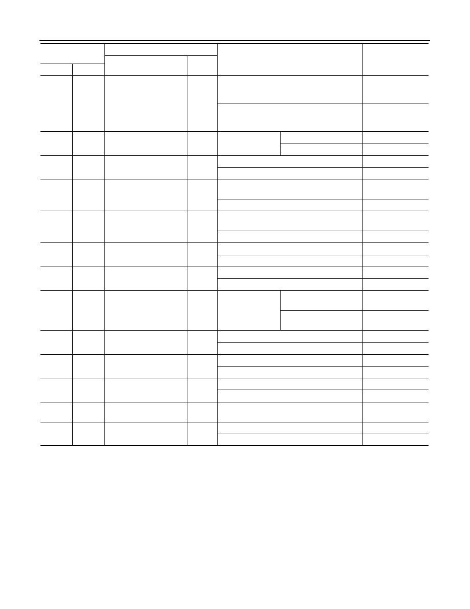
Terminal No.
(Wire color)
Description
Condition
Value
(Approx.)
Signal name
Input/
Output
+
−