Nissan Qashqai (2007-2010). Manual - part 1850


  Index      Nissan     Nissan Qashqai - service and repair manual 2007 - 2010 year


Search            copyright infringement  


Content   ..  1848  1849  1850  1851   ..


Nissan Qashqai (2007-2010). Manual - part 1850


PCS-4

< FUNCTION DIAGNOSIS >

[IPDM E/R]

RELAY CONTROL SYSTEM
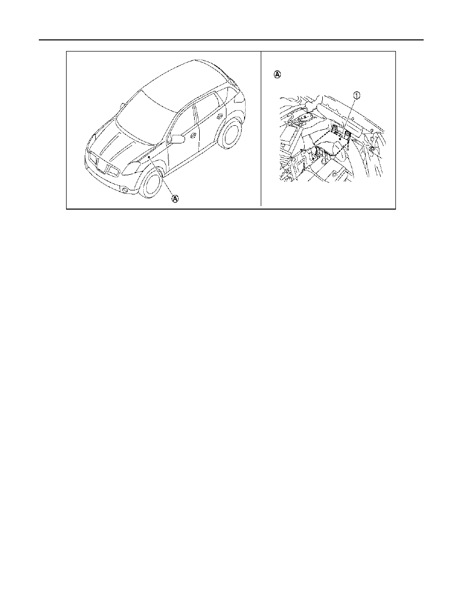
1.

IPDM E/R

A.

Engine room (left side)

JPMIA0232ZZ

PCS

SIGNAL BUFFER SYSTEM

PCS-5

< FUNCTION DIAGNOSIS >

[IPDM E/R]

C

D

E

F

G

H

I

J

K

L

B

A

O

P

N

SIGNAL BUFFER SYSTEM

System Diagram

INFOID:0000000000926985

System Description

INFOID:0000000000926986

• IPDM E/R reads the status of the oil pressure switch and transmits the oil pressure switch signal to BCM and

ECM*

1

 via CAN communication. Refer to 

MWI-15, "WARNING LAMPS/INDICATOR LAMPS : System Dia-

gram"

.

• IPDM E/R reads the status of the reverse switch and transmits the reverse switch signal to BCM and ECM*

2

via CAN communication. Refer to 

EC-1399, "DTC Logic"

.

• IPDM E/R reads the status of the hood switch and transmits the hood switch signal to BCM via CAN commu-

nication. Refer to 

SEC-19, "System Diagram"

 (with INTELLIGENT KEY system)

SEC-165, "System Dia-

gram"

 (without INTELLIGENT KEY system).

• IPDM E/R receives the front wiper auto stop signal status from front wiper motor and transmits the front

wiper auto stop signal to BCM via CAN communication. Refer to 

WW-6, "System Diagram"

.

NOTE:
• *1: HR engine and MR engine models
• *2: K9K engine models

Component Parts Location

INFOID:0000000000984483

JPMIA0233GB

JPMIA0232ZZ

PCS-6

< FUNCTION DIAGNOSIS >

[IPDM E/R]

SIGNAL BUFFER SYSTEM

1.

IPDM E/R

A.

Engine room (left side)

PCS

POWER CONSUMPTION CONTROL SYSTEM

PCS-7

< FUNCTION DIAGNOSIS >

[IPDM E/R]

C

D

E

F

G

H

I

J

K

L

B

A

O

P

N

POWER CONSUMPTION CONTROL SYSTEM

System Diagram

INFOID:0000000001109153

System Description

INFOID:0000000000926989

OUTLINE

• IPDM E/R incorporates a power consumption control function that reduces the power consumption accord-

ing to the vehicle status. 

• IPDM E/R changes its status (control mode) with the sleep wake up signal received from BCM via CAN com-

munication.

Normal mode (wake-up)

- CAN communication is normally performed with other control units.
- Individual unit control by IPDM E/R is normally performed.

Low power consumption mode (sleep)

- Low power consumption control is active.
- CAN transmission is stopped.

Sleep mode activation

• IPDM E/R judges that the sleep-ready conditions are fulfilled when the ignition switch is OFF and none of the

conditions below are present. Then it transmits a sleep-ready signal (ready) to BCM via CAN communica-
tion.

- Front wiper fail-safe operation 
- Ignition relay ON or OFF stuck detection
- Outputting signals to actuators
- Switches or relays operating
- Auto active test is starting
- Communicating with CONSULT-III
- Hood switch status is changed
- Output requests are being received from control units via CAN communication.
• IPDM E/R stops CAN communication and enters the low power consumption mode when it receives a sleep

wake up signal (sleep) from BCM and the sleep-ready conditions are fulfilled.

Wake-up operation

• IPDM E/R changes from the low power consumption mode to the normal mode when it receives a sleep

wake-up signal (wake up) from BCM or any of the following conditions is fulfilled. In addition, it transmits a
sleep-ready signal (not-ready) to BCM via CAN communication to report the CAN communication start.

- Ignition switch ON
- The hood switch status changes.
- An output request is received from a control unit via CAN communication.

Component Parts Location

INFOID:0000000001109154

JPMIA0125GB


Content   ..  1848  1849  1850  1851   ..