Nissan Qashqai (2007-2010). Manual - part 1749


  Index      Nissan     Nissan Qashqai - service and repair manual 2007 - 2010 year


Search            copyright infringement  


Content   ..  1747  1748  1749  1750   ..


Nissan Qashqai (2007-2010). Manual - part 1749


LAN

CAN COMMUNICATION CIRCUIT

LAN-1021

< COMPONENT DIAGNOSIS >

[CAN SYSTEM (TYPE 69)]

C

D

E

F

G

H

I

J

K

L

B

A

O

P

N

CAN COMMUNICATION CIRCUIT

Diagnosis Procedure

INFOID:0000000001057838

INSPECTION PROCEDURE

1.

CONNECTOR INSPECTION

1.

Turn the ignition switch OFF.

2.

Disconnect the battery cable from the negative terminal.

3.

Disconnect all the unit connectors on CAN communication system.

4.

Check terminals and connectors for damage, bend and loose connection.

Is the inspection result normal?

YES

>> GO TO 2.

NO

>> Repair the terminal and connector.

2.

CHECK HARNESS CONTINUITY (SHORT CIRCUIT)

Check the continuity between the data link connector terminals.

Is the inspection result normal?

YES

>> GO TO 3.

NO

>> Check the harness and repair the root cause.

3.

CHECK HARNESS CONTINUITY (SHORT CIRCUIT)

Check the continuity between the data link connector and the ground.

Is the inspection result normal?

YES

>> GO TO 4.

NO

>> Check the harness and repair the root cause.

4.

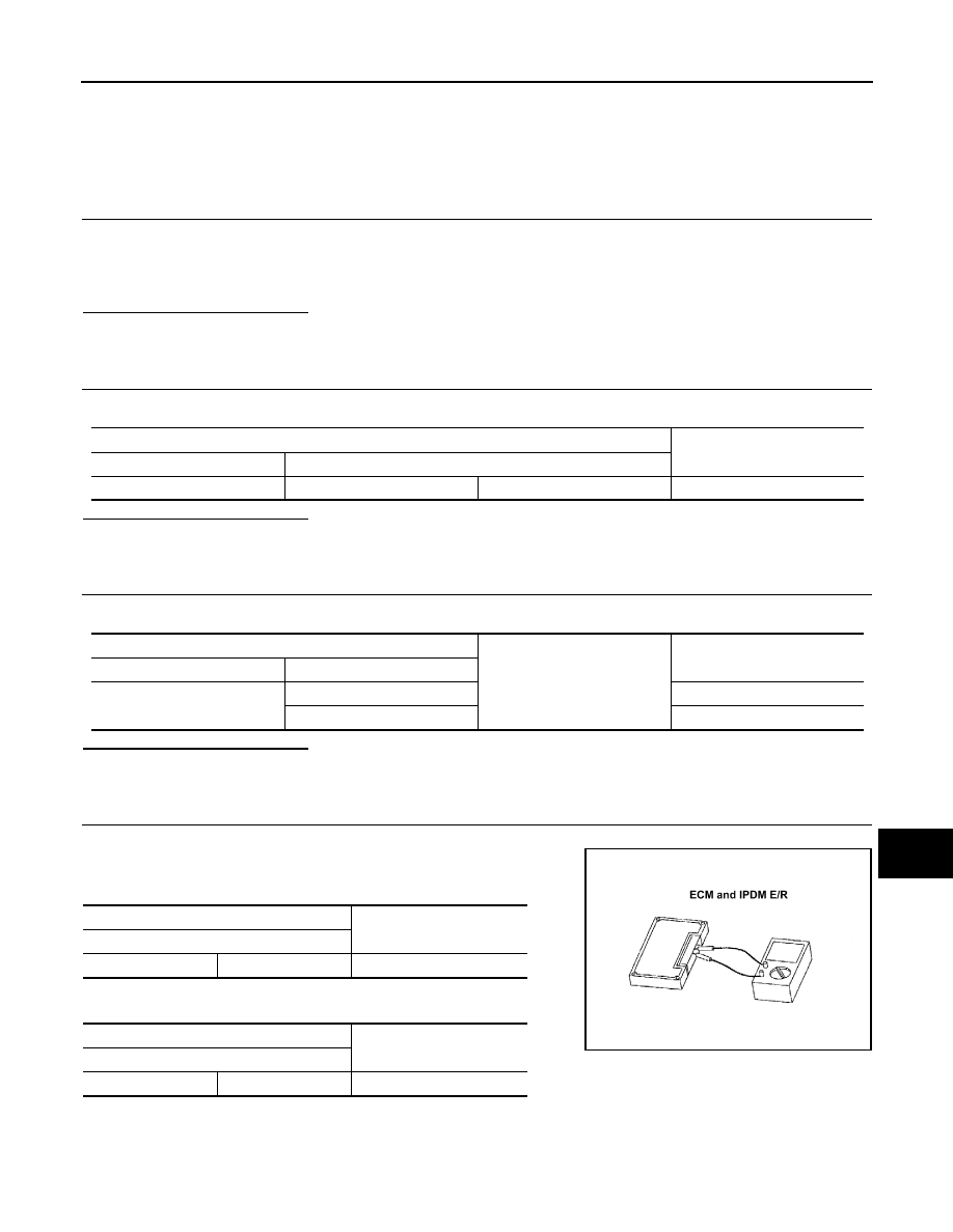
CHECK ECM AND IPDM E/R TERMINATION CIRCUIT

1.

Remove the ECM and the IPDM E/R.

2.

Check the resistance between the ECM terminals.

-

HR engine/MR engine models

-

K9K engine models

3.

Check the resistance between the IPDM E/R terminals.

Data link connector

Continuity

Connector No.

Terminal No.

M4

6

14

Not existed

Data link connector

Ground

Continuity

Connector No.

Terminal No.

M4

6

Not existed

14

Not existed

ECM

Resistance (

)

Terminal No.

84

83

Approx. 108 – 132

ECM

Resistance (

)

Terminal No.

100

99

Approx. 108 – 132

LKIA0037E

LAN-1022

< COMPONENT DIAGNOSIS >

[CAN SYSTEM (TYPE 69)]

CAN COMMUNICATION CIRCUIT

Is the measurement value within the specification?

YES

>> GO TO 5.

NO

>> Replace the ECM and/or the IPDM E/R.

5.

CHECK SYMPTOM

Connect all the connectors. Check if the symptoms described in the “Symptom (Results from interview with
customer)” are reproduced. 

Inspection result

Reproduced>>GO TO 6.
Non-reproduced>>Start the diagnosis again. Follow the trouble diagnosis procedure when past error is

detected.

6.

CHECK UNIT REPRODUCTION

Perform the reproduction test as per the following procedure for each unit.
1.

Turn the ignition switch OFF.

2.

Disconnect the battery cable from the negative terminal.

3.

Disconnect one of the unit connectors of CAN communication system.
NOTE:
ECM and IPDM E/R have a termination circuit. Check other units first.

4.

Connect the battery cable to the negative terminal. Check if the symptoms described in the “Symptom
(Results from interview with customer)” are reproduced. 
NOTE:
Although unit-related error symptoms occur, do not confuse them with other symptoms. 

Inspection result

Reproduced>>Connect the connector. Check other units as per the above procedure.
Non-reproduced>>Replace the unit whose connector was disconnected.

IPDM E/R

Resistance (

)

Terminal No.

28

29

Approx. 108 – 132

LAN

MAIN LINE BETWEEN ABS AND BCM CIRCUIT

LAN-1023

< COMPONENT DIAGNOSIS >

[CAN SYSTEM (TYPE 70)]

C

D

E

F

G

H

I

J

K

L

B

A

O

P

N

COMPONENT DIAGNOSIS

MAIN LINE BETWEEN ABS AND BCM CIRCUIT

Diagnosis Procedure

INFOID:0000000001057869

INSPECTION PROCEDURE

1.

CHECK CONNECTOR

1.

Turn the ignition switch OFF.

2.

Disconnect the battery cable from the negative terminal.

3.

Check the following terminals and connectors for damage, bend and loose connection (connector side
and harness side).

-

Harness connector E105

-

Harness connector M77

Is the inspection result normal?

YES

>> GO TO 2.

NO

>> Repair the terminal and connector.

2.

CHECK HARNESS CONTINUITY (OPEN CIRCUIT)

1.

Disconnect the following harness connectors.

-

ABS actuator and electric unit (control unit)

-

Harness connectors E105 and M77

2.

Check the continuity between the ABS actuator and electric unit (control unit) and the harness connector.

-

Models with ESP

-

Models with ABS

Is the inspection result normal?

YES

>> GO TO 3.

NO

>> Repair the main line between the ABS actuator and electric unit (control unit) harness connector

and the harness connector E105.

3.

CHECK HARNESS CONTINUITY (OPEN CIRCUIT)

1.

Disconnect the connector of BCM.

2.

Check the continuity between the harness connector and the BCM harness connector.

Is the inspection result normal?

YES (Present error)>>Check CAN system type decision again.
YES (Past error)>>Error was detected in the main line between the ABS actuator and electric unit (control

unit) and the BCM. 

ABS actuator and electric unit (control unit)

harness connector

Harness connector

Continuity

Connector No.

Terminal No.

Connector No.

Terminal No.

E36

26

E105

52

Existed

15

51

Existed

ABS actuator and electric unit (control unit)

harness connector

Harness connector

Continuity

Connector No.

Terminal No.

Connector No.

Terminal No.

E34

26

E105

52

Existed

15

51

Existed

Harness connector

BCM harness connector

Continuity

Connector No.

Terminal No.

Connector No.

Terminal No.

M77

52

M65

19

Existed

51

20

Existed

LAN-1024

< COMPONENT DIAGNOSIS >

[CAN SYSTEM (TYPE 70)]

MAIN LINE BETWEEN ABS AND BCM CIRCUIT

NO

>> Repair the main line between the harness connector M77 and the BCM.


Content   ..  1747  1748  1749  1750   ..