Nissan Qashqai (2007-2010). Manual - part 1693


  Index      Nissan     Nissan Qashqai - service and repair manual 2007 - 2010 year


Search            copyright infringement  


Content   ..  1691  1692  1693  1694   ..


Nissan Qashqai (2007-2010). Manual - part 1693


LAN

ECM BRANCH LINE CIRCUIT

LAN-797

< COMPONENT DIAGNOSIS >

[CAN SYSTEM (TYPE 53)]

C

D

E

F

G

H

I

J

K

L

B

A

O

P

N

ECM BRANCH LINE CIRCUIT

Diagnosis Procedure

INFOID:0000000001057026

1.

CHECK CONNECTOR

1.

Turn the ignition switch OFF.

2.

Disconnect the battery cable from the negative terminal.

3.

Check the terminals and connectors of the ECM for damage, bend and loose connection (unit side and
connector side).

Is the inspection result normal?

YES

>> GO TO 2.

NO

>> Repair the terminal and connector.

2.

CHECK HARNESS FOR OPEN CIRCUIT

1.

Disconnect the connector of ECM.

2.

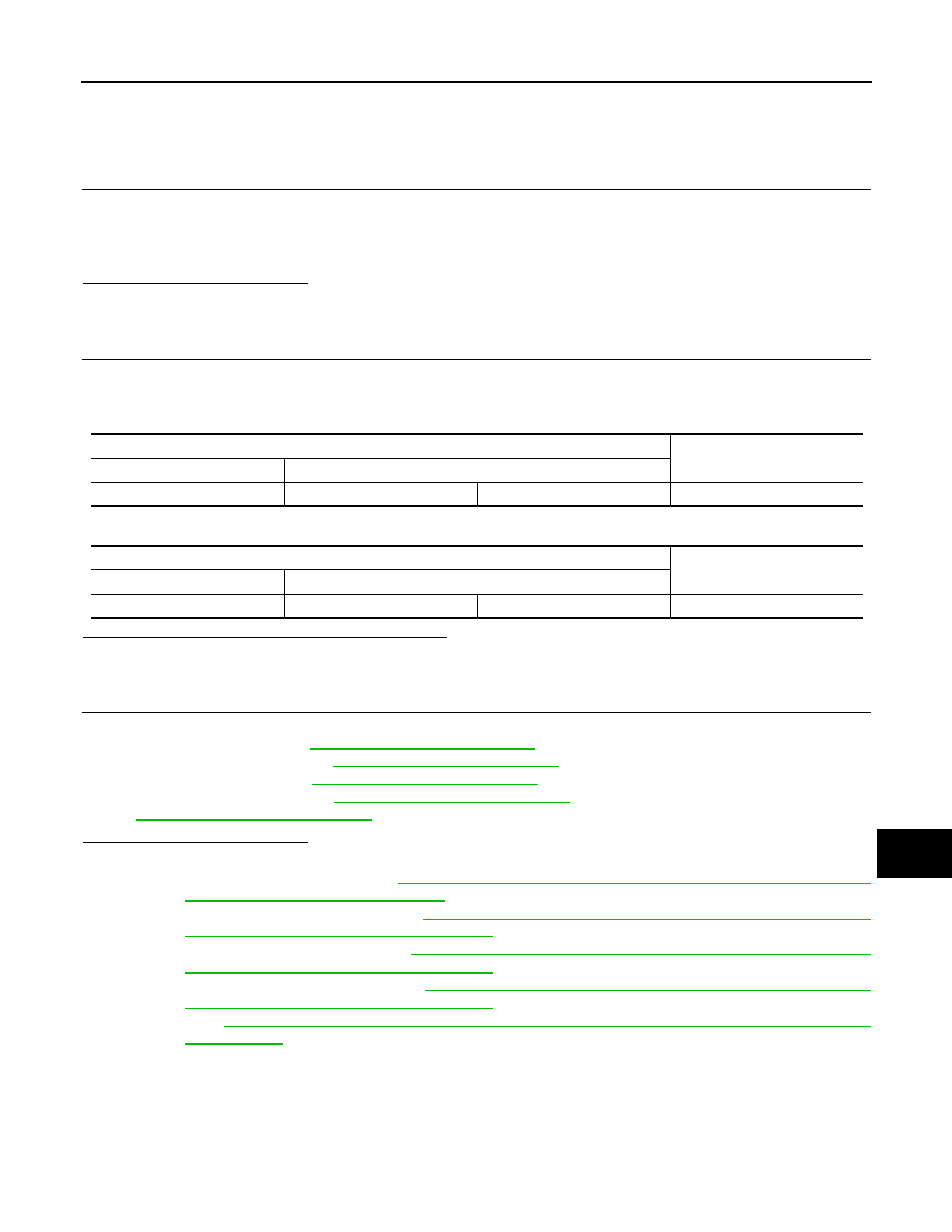
Check the resistance between the ECM harness connector terminals.

-

HR engine/MR engine models

-

K9K engine models

Is the measurement value within the specification?

YES

>> GO TO 3.

NO

>> Repair the ECM branch line.

3.

CHECK POWER SUPPLY AND GROUND CIRCUIT

Check the power supply and the ground circuit of the ECM. Refer to the following.
• HR16DE (With EURO-OBD): 

EC-117, "Diagnosis Procedure"

• HR16DE (Without EURO-OBD): 

EC-446, "Diagnosis Procedure"

• MR20DE (With EURO-OBD): 

EC-736, "Diagnosis Procedure"

• MR20DE (Without EURO-OBD): 

EC-1069, "Diagnosis Procedure"

• K9K: 

EC-1317, "Diagnosis Procedure"

Is the inspection result normal?

YES (Present error)>>•Replace the ECM. Refer to the following.

- HR16DE (With EURO-OBD): 

EC-29, "ADDITIONAL SERVICE WHEN REPLACING CONTROL

UNIT : Special Repair Requirement"

HR16DE (Without EURO-OBD): 

EC-368, "ADDITIONAL SERVICE WHEN REPLACING CON-

TROL UNIT : Special Repair Requirement"

- MR20DE (With EURO-OBD): 

EC-645, "ADDITIONAL SERVICE WHEN REPLACING CON-

TROL UNIT : Special Repair Requirement"

- MR20DE (Without EURO-OBD): 

EC-989, "ADDITIONAL SERVICE WHEN REPLACING CON-

TROL UNIT : Special Repair Requirement"

- K9K: 

EC-1273, "ADDITIONAL SERVICE WHEN REPLACING CONTROL UNIT : Special Repair

Requirement"

YES (Past error)>>Error was detected in the ECM branch line.
NO

>> Repair the power supply and the ground circuit.

ECM harness connector

Resistance (

)

Connector No.

Terminal No.

E16

84

83

Approx. 108 – 132

ECM harness connector

Resistance (

)

Connector No.

Terminal No.

E60

100

99

Approx. 108 – 132

LAN-798

< COMPONENT DIAGNOSIS >

[CAN SYSTEM (TYPE 53)]

ABS BRANCH LINE CIRCUIT

ABS BRANCH LINE CIRCUIT

Diagnosis Procedure

INFOID:0000000001057027

1.

CHECK CONNECTOR

1.

Turn the ignition switch OFF.

2.

Disconnect the battery cable from the negative terminal.

3.

Check the terminals and connectors of the ABS actuator and electric unit (control unit) for damage, bend
and loose connection (unit side and connector side).

Is the inspection result normal?

YES

>> GO TO 2.

NO

>> Repair the terminal and connector.

2.

CHECK HARNESS FOR OPEN CIRCUIT

1.

Disconnect the connector of ABS actuator and electric unit (control unit).

2.

Check the resistance between the ABS actuator and electric unit (control unit) harness connector termi-
nals.

-

Models with ESP

-

Models with ABS

Is the measurement value within the specification?

YES

>> GO TO 3.

NO

>> Repair the ABS actuator and electric unit (control unit) branch line.

3.

CHECK POWER SUPPLY AND GROUND CIRCUIT

Check the power supply and the ground circuit of the ABS actuator and electric unit (control unit). Refer to the
following.
• ABS models: 

BRC-26, "Diagnosis Procedure"

• ESP models: 

BRC-106, "Diagnosis Procedure"

Is the inspection result normal?

YES (Present error)>>•Replace the ABS actuator and electric unit (control unit). Refer to 

BRC-70, "Exploded

View"

.

YES (Past error)>>Error was detected in the ABS actuator and electric unit (control unit) branch line.
NO

>> Repair the power supply and the ground circuit.

ABS actuator and electric unit (control unit) harness connector

Resistance (

)

Connector No.

Terminal No.

E36

26

15

Approx. 54 – 66

ABS actuator and electric unit (control unit) harness connector

Resistance (

)

Connector No.

Terminal No.

E34

26

15

Approx. 54 – 66

LAN

BCM BRANCH LINE CIRCUIT

LAN-799

< COMPONENT DIAGNOSIS >

[CAN SYSTEM (TYPE 53)]

C

D

E

F

G

H

I

J

K

L

B

A

O

P

N

BCM BRANCH LINE CIRCUIT

Diagnosis Procedure

INFOID:0000000001057030

1.

CHECK CONNECTOR

1.

Turn the ignition switch OFF.

2.

Disconnect the battery cable from the negative terminal.

3.

Check the terminals and connectors of the BCM for damage, bend and loose connection (unit side and
connector side).

Is the inspection result normal?

YES

>> GO TO 2.

NO

>> Repair the terminal and connector.

2.

CHECK HARNESS FOR OPEN CIRCUIT

1.

Disconnect the connector of BCM.

2.

Check the resistance between the BCM harness connector terminals.

Is the measurement value within the specification?

YES

>> GO TO 3.

NO

>> Repair the BCM branch line.

3.

CHECK POWER SUPPLY AND GROUND CIRCUIT

Check the power supply and the ground circuit of the BCM. Refer to 

BCS-34, "Diagnosis Procedure"

.

Is the inspection result normal?

YES (Present error)>>Replace the BCM. Refer to 

BCS-64, "Exploded View"

.

YES (Past error)>>Error was detected in the BCM branch line.
NO

>> Repair the power supply and the ground circuit.

BCM harness connector

Resistance (

)

Connector No.

Terminal No.

M65

19

20

Approx. 54 – 66

LAN-800

< COMPONENT DIAGNOSIS >

[CAN SYSTEM (TYPE 53)]

M&A BRANCH LINE CIRCUIT

M&A BRANCH LINE CIRCUIT

Diagnosis Procedure

INFOID:0000000001057031

INSPECTION PROCEDURE

1.

CHECK CONNECTOR

1.

Turn the ignition switch OFF.

2.

Disconnect the battery cable from the negative terminal.

3.

Check the terminals and connectors of the combination meter for damage, bend and loose connection
(unit side and connector side).

Is the inspection result normal?

YES

>> GO TO 2.

NO

>> Repair the terminal and connector.

2.

CHECK HARNESS FOR OPEN CIRCUIT

1.

Disconnect the connector of combination meter.

2.

Check the resistance between the combination meter harness connector terminals.

Is the measurement value within the specification?

YES

>> GO TO 3.

NO

>> Repair the combination meter branch line.

3.

CHECK POWER SUPPLY AND GROUND CIRCUIT

Check the power supply and the ground circuit of the combination meter. Refer to  

MWI-28, "COMBINATION

METER : Diagnosis Procedure"

.

Is the inspection result normal?

YES (Present error)>>Replace the combination meter. Refer to  

MWI-72, "Exploded View"

.

YES (Past error)>>Error was detected in the combination meter branch line.
NO

>> Repair the power supply and the ground circuit.

Combination meter harness connector

Resistance (

)

Connector No.

Terminal No.

M34

21

22

Approx. 54 – 66


Content   ..  1691  1692  1693  1694   ..