Nissan Qashqai (2007-2010). Manual - part 1569


  Index      Nissan     Nissan Qashqai - service and repair manual 2007 - 2010 year


Search            copyright infringement  


Content   ..  1567  1568  1569  1570   ..


Nissan Qashqai (2007-2010). Manual - part 1569


LAN

EPS BRANCH LINE CIRCUIT

LAN-301

< COMPONENT DIAGNOSIS >

[CAN SYSTEM (TYPE 17)]

C

D

E

F

G

H

I

J

K

L

B

A

O

P

N

EPS BRANCH LINE CIRCUIT

Diagnosis Procedure

INFOID:0000000001101059

INSPECTION PROCEDURE

1.

CHECK CONNECTOR

1.

Turn the ignition switch OFF.

2.

Disconnect the battery cable from the negative terminal.

3.

Check the terminals and connectors of the EPS control unit for damage, bend and loose connection (unit
side and connector side).

Is the inspection result normal?

YES

>> GO TO 2.

NO

>> Repair the terminal and connector.

2.

CHECK HARNESS FOR OPEN CIRCUIT

1.

Disconnect the connector of EPS control unit.

2.

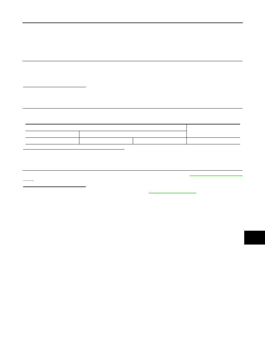
Check the resistance between the EPS control unit harness connector terminals.

Is the measurement value within the specification?

YES

>> GO TO 3.

NO

>> Repair the EPS control unit branch line.

3.

CHECK POWER SUPPLY AND GROUND CIRCUIT

Check the power supply and the ground circuit of the EPS control unit. Refer to 

STC-8, "Diagnosis Proce-

dure"

.

Is the inspection result normal?

YES (Present error)>>Replace the EPS control unit. Refer to 

ST-10, "Exploded View"

.

YES (Past error)>>Error was detected in the EPS control unit branch line.
NO

>> Repair the power supply and the ground circuit.

EPS control unit harness connector

Resistance (

)

Connector No.

Terminal No.

M37

8

6

Approx. 54 – 66

LAN-302

< COMPONENT DIAGNOSIS >

[CAN SYSTEM (TYPE 17)]

IPDM-E BRANCH LINE CIRCUIT

IPDM-E BRANCH LINE CIRCUIT

Diagnosis Procedure

INFOID:0000000001101062

INSPECTION PROCEDURE

1.

CHECK CONNECTOR

1.

Turn the ignition switch OFF.

2.

Disconnect the battery cable from the negative terminal.

3.

Check the following terminals and connectors for damage, bend and loose connection (unit side and con-
nector side).

-

IPDM E/R connector

-

Harness connector E105

-

Harness connector M77

Is the inspection result normal?

YES

>> GO TO 2.

NO

>> Repair the terminal and connector.

2.

CHECK HARNESS FOR OPEN CIRCUIT

1.

Disconnect the connector of IPDM E/R.

2.

Check the resistance between the IPDM E/R harness connector terminals.

Is the measurement value within the specification?

YES

>> GO TO 3.

NO

>> Repair the IPDM E/R branch line.

3.

CHECK POWER SUPPLY AND GROUND CIRCUIT

Check the power supply and the ground circuit of the IPDM E/R. Refer to 

PCS-18, "Diagnosis Procedure"

.

Is the inspection result normal?

YES (Present error)>>Replace the IPDM E/R. Refer to 

PCS-32, "Exploded View"

.

YES (Past error)>>Error was detected in the IPDM E/R branch line.
NO

>> Repair the power supply and the ground circuit.

IPDM E/R harness connector

Resistance (

)

Connector No.

Terminal No.

E12

28

29

Approx. 108 – 132

LAN

CAN COMMUNICATION CIRCUIT

LAN-303

< COMPONENT DIAGNOSIS >

[CAN SYSTEM (TYPE 17)]

C

D

E

F

G

H

I

J

K

L

B

A

O

P

N

CAN COMMUNICATION CIRCUIT

Diagnosis Procedure

INFOID:0000000001101063

INSPECTION PROCEDURE

1.

CONNECTOR INSPECTION

1.

Turn the ignition switch OFF.

2.

Disconnect the battery cable from the negative terminal.

3.

Disconnect all the unit connectors on CAN communication system.

4.

Check terminals and connectors for damage, bend and loose connection.

Is the inspection result normal?

YES

>> GO TO 2.

NO

>> Repair the terminal and connector.

2.

CHECK HARNESS CONTINUITY (SHORT CIRCUIT)

Check the continuity between the data link connector terminals.

Is the inspection result normal?

YES

>> GO TO 3.

NO

>> Check the harness and repair the root cause.

3.

CHECK HARNESS CONTINUITY (SHORT CIRCUIT)

Check the continuity between the data link connector and the ground.

Is the inspection result normal?

YES

>> GO TO 4.

NO

>> Check the harness and repair the root cause.

4.

CHECK ECM AND IPDM E/R TERMINATION CIRCUIT

1.

Remove the ECM and the IPDM E/R.

2.

Check the resistance between the ECM terminals.

-

HR engine/MR engine models

-

K9K engine models

3.

Check the resistance between the IPDM E/R terminals.

Data link connector

Continuity

Connector No.

Terminal No.

M4

6

14

Not existed

Data link connector

Ground

Continuity

Connector No.

Terminal No.

M4

6

Not existed

14

Not existed

ECM

Resistance (

)

Terminal No.

84

83

Approx. 108 – 132

ECM

Resistance (

)

Terminal No.

100

99

Approx. 108 – 132

LKIA0037E

LAN-304

< COMPONENT DIAGNOSIS >

[CAN SYSTEM (TYPE 17)]

CAN COMMUNICATION CIRCUIT

Is the measurement value within the specification?

YES

>> GO TO 5.

NO

>> Replace the ECM and/or the IPDM E/R.

5.

CHECK SYMPTOM

Connect all the connectors. Check if the symptoms described in the “Symptom (Results from interview with
customer)” are reproduced. 

Inspection result

Reproduced>>GO TO 6.
Non-reproduced>>Start the diagnosis again. Follow the trouble diagnosis procedure when past error is

detected.

6.

CHECK UNIT REPRODUCTION

Perform the reproduction test as per the following procedure for each unit.
1.

Turn the ignition switch OFF.

2.

Disconnect the battery cable from the negative terminal.

3.

Disconnect one of the unit connectors of CAN communication system.
NOTE:
ECM and IPDM E/R have a termination circuit. Check other units first.

4.

Connect the battery cable to the negative terminal. Check if the symptoms described in the “Symptom
(Results from interview with customer)” are reproduced. 
NOTE:
Although unit-related error symptoms occur, do not confuse them with other symptoms. 

Inspection result

Reproduced>>Connect the connector. Check other units as per the above procedure.
Non-reproduced>>Replace the unit whose connector was disconnected.

IPDM E/R

Resistance (

)

Terminal No.

28

29

Approx. 108 – 132


Content   ..  1567  1568  1569  1570   ..