Nissan Qashqai (2007-2010). Manual - part 1126


  Index      Nissan     Nissan Qashqai - service and repair manual 2007 - 2010 year


Search            copyright infringement  


Content   ..  1124  1125  1126  1127   ..


Nissan Qashqai (2007-2010). Manual - part 1126


U1010 CONTROL UNIT (CAN)

DLK-583

< COMPONENT DIAGNOSIS >

[WITHOUT I-KEY & SUPER LOCK]

C

D

E

F

G

H

I

J

L

M

A

B

DLK

N

O

P

U1010 CONTROL UNIT (CAN)

DTC Logic

INFOID:0000000001097218

DTC DETECTION LOGIC

Diagnosis Procedure

INFOID:0000000001097219

1.

REPLACE BCM

When “DTC:U1010” is detected, replace BCM.

>> Replace BCM. Refer to 

BCS-64, "Exploded View"

.

Special Repair Requirement

INFOID:0000000001097220

1.

ADDITIONAL SERVICE WHEN REPLACING BCM

>> Refer to 

BCS-3, "ADDITIONAL SERVICE WHEN REPLACING CONTROL UNIT : Description"
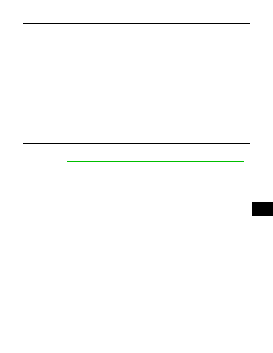
.

DTC

CONSULT-III display de-

scription

DTC Detection Condition

Possible cause

U1010

CONTROL UNIT (CAN)

When detecting error during the initial diagnosis of CAN control-
ler of BCM.

BCM

DLK-584

< COMPONENT DIAGNOSIS >

[WITHOUT I-KEY & SUPER LOCK]

POWER SUPPLY AND GROUND CIRCUIT

POWER SUPPLY AND GROUND CIRCUIT

BCM

BCM : Diagnosis Procedure

INFOID:0000000001115315

1.

CHECK FUSE AND FUSIBLE LINK

Check that the following fuse and fusible link are not blown.

Is the fuse fusing?

YES

>> Replace the blown fuse or fusible link after repairing the affected circuit if a fuse or fusible link is

blown.

NO

>> GO TO 2.

2.

CHECK POWER SUPPLY CIRCUIT

1.

Turn ignition switch OFF.

2.

Disconnect BCM connectors.

3.

Check voltage between BCM harness connector and ground.

Is the measurement value normal?

YES

>> GO TO 3.

NO

>> Repair harness or connector.

3.

CHECK GROUND CIRCUIT

Check continuity between BCM harness connector and ground.

Does continuity exist?

YES

>> BCM power supply and ground circuit are OK.

NO

>> Repair harness or connector.

Terminal No.

Signal name

Fuse and fusible link No.

41

Battery power supply

9 (10A)

57

J (40A)

Terminals

Voltage

(Approx.)

(+)

(

)

BCM

Ground

Connector

Terminal

M66

41

Battery voltage

M67

57

BCM

Ground

Continuity

Connector

Terminal

M67

55

Existed

DOOR LOCK AND UNLOCK SWITCH

DLK-585

< COMPONENT DIAGNOSIS >

[WITHOUT I-KEY & SUPER LOCK]

C

D

E

F

G

H

I

J

L

M

A

B

DLK

N

O

P

DOOR LOCK AND UNLOCK SWITCH

Description

INFOID:0000000001099004

Transmits door lock/unlock operation to BCM.

Component Function Check

INFOID:0000000001099005

1.

CHECK FUNCTION

With CONSULT-III

Check “CDL LOCK SW ”and “CDL UNLOCK SW” in Data monitor mode with CONSULT-III.

Is the inspection result normal?

YES

>> Door lock and unlock switch is OK.

NO

>> Refer to 

DLK-585, "Diagnosis Procedure"

.

Diagnosis Procedure

INFOID:0000000001099006

1.

CHECK DOOR LOCK AND UNLOCK INPUT SIGNAL

1.

Turn ignition switch OFF.

2.

Disconnect door lock and unlock switch connector.

3.

Check voltage between door lock and unlock switch and ground.

Is the inspection result normal?

YES

>> GO TO 3.

NO

>> GO TO 2.

2.

CHECK DOOR LOCK AND UNLOCK SWITCH CIRCUIT

1.

Turn ignition switch OFF.

2.

Disconnect BCM connector.

3.

Check continuity between BCM connector and door lock and unlock switch connector.

4.

Check continuity between BCM connector and ground.

Monitor item

Condition

CDL LOCK SW 

LOCK

: ON

UNLOCK

: OFF

CDL UNLOCK SW 

LOCK

: OFF

UNLOCK

: ON

Terminal

Signal

(Reference value)

(+)

(–)

Door lock and unlock switch 

connector

Terminal 

M89

1

Ground

6

JPMIA0154GB

BCM connector

Terminal

Door lock and unlock 

switch connector

Terminal

Continuity 

M65

7

M89

6

Exists

9

1

DLK-586

< COMPONENT DIAGNOSIS >

[WITHOUT I-KEY & SUPER LOCK]

DOOR LOCK AND UNLOCK SWITCH

Is the inspection result normal?

YES

>> GO TO 4.

NO

>> Repair or replace harness.

3.

CHECK DOOR LOCK AND UNLOCK SWITCH GROUND 

Check continuity between door lock and unlock switch connector and ground.

Is the inspection result normal?

YES

>> GO TO 5.

NO

>> Repair or replace harness.

4.

CHECK BCM OUTPUT SIGNAL

1.

Connect BCM connector.

2.

Check voltage between BCM connector and ground.

Is the inspection result normal?

YES

>> Check intermittent incident. Refer to 

GI-39, "Intermittent Incident"

.

NO

>> Replace BCM. Refer to 

BCS-64, "Exploded View"

.

5.

CHECK DOOR LOCK AND UNLOCK SWITCH

Check door lock and unlock switch
Refer to 

DLK-74, "Component Inspection"

.

Is the inspection result normal?

YES

>> Check intermittent incident. Refer to 

GI-39, "Intermittent Incident"

.

NO

>> Replace door lock and unlock switch. Refer to 

DLK-280, "Exploded View"

.

Component Inspection

INFOID:0000000001099007

1.

CHECK DOOR LOCK AND UNLOCK SWITCH

Check door lock and unlock switch.

Is the inspection result normal?

YES

>> Door lock and unlock switch is OK.

NO

>> Replace door lock and unlock switch. Refer to 

DLK-280, "Exploded View"

.

BCM connector

Terminal

Ground

Continuity

M65

7

Does not exist

9

Door lock and unlock switch connector

Terminal

Ground

Continuity 

M89

5

Exists

Terminal

Signal

(Reference value)

(+)

(–)

BCM connector

Terminal 

M65

7

Ground

9

JPMIA0154GB

Door lock and unlock switch

Terminal

Condition

Continuity

M89

6

5

LOCK

Exists

1

UNLOCK


Content   ..  1124  1125  1126  1127   ..