Nissan Qashqai (2007-2010). Manual - part 66


  Index      Nissan     Nissan Qashqai - service and repair manual 2007 - 2010 year


Search            copyright infringement  


Content   ..  64  65  66  67   ..


Nissan Qashqai (2007-2010). Manual - part 66


EM-212

< DISASSEMBLY AND ASSEMBLY >

[MR20DE]

CYLINDER BLOCK

CAUTION:

When removing them, note the installation position. Keep them in the correct.
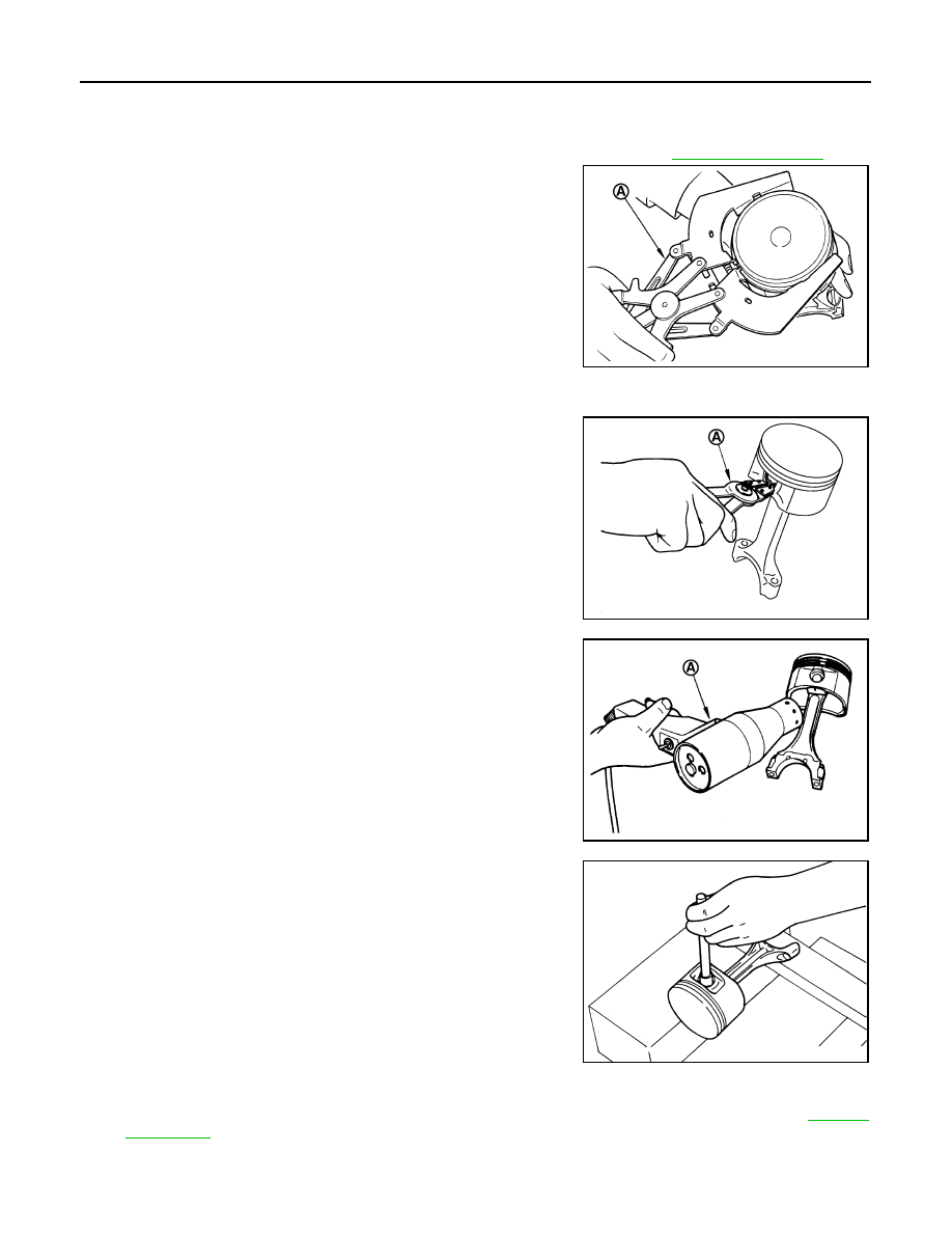
9.

Remove piston rings form piston. 
• Before removing piston rings, check the piston ring side clearance. Refer to 

EM-219, "Inspection"

.

• Use a piston ring expander (commercial service tool) (A).

CAUTION:

• When removing piston rings, be careful not to damage

the piston.

• Be careful not to damage piston rings by expanding

them excessively.

10. Remove piston from connecting rod with the following procedure: 
a.

Using snap ring pliers (A), remove snap rings.

b.

Heat piston to 60 to 70

°

C (140 to 158

°

F) with an industrial use

drier (A) or equivalent.

c.

Push out piston pin with stick of outer diameter approximately 18
mm (0.71 in).

11. Remove main bearing cap mounting bolts.

• Measure crankshaft end play before loosening main bearing cap mounting bolts. Refer to 

EM-219,

"Inspection"

.

PBIC3233J

PBIC3230J

PBIC3231J

PBIC0262E

CYLINDER BLOCK

EM-213

< DISASSEMBLY AND ASSEMBLY >

[MR20DE]

C

D

E

F

G

H

I

J

K

L

M

A

EM

N

P

O

• Loosen and remove bolts in reverse order as shown in the fig-

ure.

• Use TORX socket (size E14).

12. Remove main bearing caps.

• Tap main bearing caps lightly with a plastic hammer for removal. 

CAUTION:

Be careful not to damage the mounting surface.

13. Remove crankshaft.

CAUTION:

• Be careful not to damage or deform signal plate (1)

mounted on rear end of crankshaft (A).

• When setting crankshaft on a flat floor surface, use a

block of wood to avoid interference between signal plate
and the floor surface.

• Never remove signal plate unless it is necessary to do so.
NOTE:
When removing or installing signal plate, use TORX socket (size
T30).

14. Pull rear oil seal out from rear end of crankshaft.
15. Remove main bearings and thrust bearings from cylinder block and main bearing caps.

CAUTION:

Identify installation positions, and store them without mixing them up.

Assembly

1.

Fully air-blow engine coolant and engine oil passages in cylinder block, cylinder bore and crankcase to
remove any foreign material.

CAUTION:

Use a goggles to protect your eye.

2.

Install each plug to cylinder block as shown in the figure.

• Apply liquid gasket to the thread of water drain plug (4).

Use Genuine Liquid Gasket or equivalent.

• Apply sealant to the thread of plug (1).

Use Thread Locking Sealant or equivalent.
NOTE:
Do not apply liquid gasket or thread locking sealant to the plug
(3).

• Tighten each plug as specified below.

: Engine front

PBIC3235J

PBIC3234J

2

:  Washer

: Engine front

PBIC3999E

Part

Washer

Tightening torque

1

Yes

54.0 N·m (5.5 kg-m, 40 ft-lb)

EM-214

< DISASSEMBLY AND ASSEMBLY >

[MR20DE]

CYLINDER BLOCK

3.

Install main bearings and thrust bearings with the following procedure:

a.

Remove dust, dirt, and engine oil on the bearing mating surfaces of cylinder block and main bearing cap.

b.

Install thrust bearings to the both sides of the No. 3 journal hous-
ing (B) on cylinder block.

• Install thrust bearings with the oil groove (A) facing crankshaft

arm (outside). 

c.

Install the main bearings paying attention to the direction.
• Before installing main bearings, apply new engine oil to the bearing surface (inside). Do not apply new

engine oil to the back surface, but thoroughly clean it.

• When installing, align main bearing to the center position of cylinder block and main bearing cap.
• The difference (A) between main bearing upper (1) and main

bearing lower (3) should be 0.85 mm (0.033 in) or less when
installing.

• Ensure the oil holes on cylinder block and oil holes (A) on the

main bearings (1) are aligned.

4.

Install signal plate to crankshaft if removed.

a.

Set the signal plate with the flange facing toward the counter weight side (engine front side) to the crank-
shaft rear surface.

b.

Apply new engine oil to threads and seat surfaces of mounting bolts.

3

No

19.6 N·m (2.0 kg-m, 14 ft-lb)

4

No

9.8 N·m (1.0 kg-m, 87 in-lb)

: Engine front

Part

Washer

Tightening torque

PBIC3258J

2

: Cylinder block

4

: Main bearing cap

PBIC3237J

PBIC3236J

CYLINDER BLOCK

EM-215

< DISASSEMBLY AND ASSEMBLY >

[MR20DE]

C

D

E

F

G

H

I

J

K

L

M

A

EM

N

P

O

c.

Position crankshaft (2) and signal plate (1) using a dowel pin
(service part), and tighten mounting bolts in numerical order as
shown in the figure using TORX socket.

NOTE:
Dowel pin of crankshaft and signal plate is provided as a set for
each.

d.

Tighten mounting bolts in numerical order as shown in the figure
again.

e.

Remove dowel pin. (service parts)

CAUTION:

Be sure to remove dowel pin.

5.

Install crankshaft to cylinder block.
• While turning crankshaft by hand, make sure that it turns smoothly. 

6.

Install main bearing caps with the following procedure:

a.

Install main bearing caps referring to the journal No. stamp (A)
and front mark (B) as shown in the figure. 

NOTE:
Main bearing cap cannot be replaced as a single part, because it
is machined together with cylinder block.

b.

Tighten main bearing cap bolts in numerical order as shown in
the figure with the following procedure:

i.

Apply new engine oil to threads and seat surfaces of mounting
bolts.

ii.

Tighten main bearing cap bolts.

iii.

Turn main bearing cap bolts 60 degrees clockwise (angle tight-
ening) in order from No. 1 to 10 in the figure.

CAUTION:

Confirm the tightening angle by using an angle wrench
[SST: KV10112100] (A) or protractor. Never judge by visual
inspection without the tool. 

• After installing mounting bolts, make sure that crankshaft can be rotated smoothly by hand.
• Check crankshaft end play. Refer to 

EM-219, "Inspection"

.

7.

Install piston to connecting rod with the following procedure: 

a.

Using snap ring pliers, install new snap ring to the groove of the piston rear side. 
• Insert it fully into groove to install. 

b.

Assemble piston to connecting rod.

A

: Dowel pin hole

: Engine front

PBIC3238J

PBIC3239J

: Engine front

: 34.3 N·m (3.5 kg-m, 25 ft-lb)

PBIC3235J

PBIC3240J


Content   ..  64  65  66  67   ..