Nissan Qashqai (2007-2010). Manual - part 51
EM-152
< ON-VEHICLE REPAIR >
[MR20DE]
OIL PAN (LOWER)
OIL PAN (LOWER)
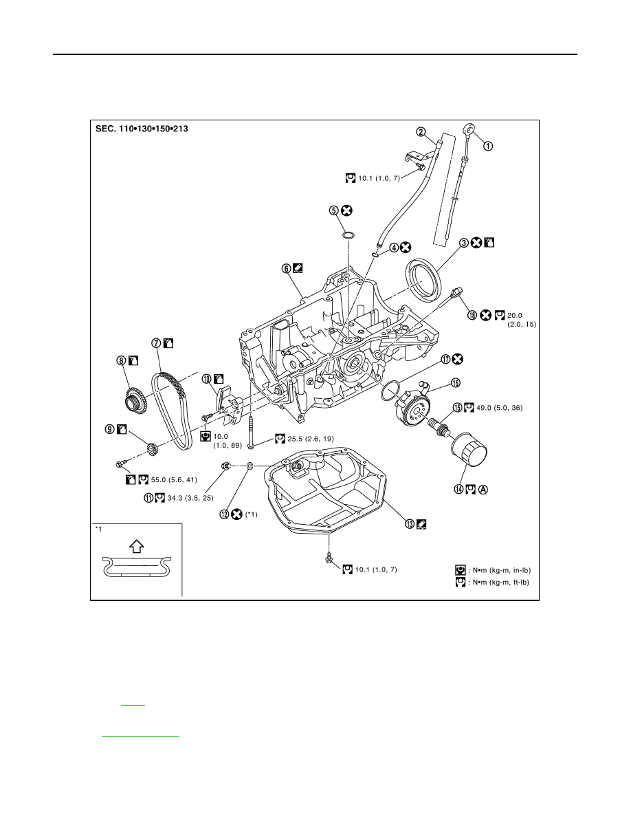
Exploded View
INFOID:0000000000893937
Removal and Installation
INFOID:0000000000893938
1.
Oil level gauge
2.
Oil level gauge guide
3.
Rear oil seal
4.
O-ring
5.
O-ring
6.
Oil pan (upper)
7.
Balancer unit timing chain
8.
Crankshaft sprocket
9.
Balancer unit sprocket
10. Balancer unit timing chain tensioner
11.
Drain plug
12. Drain plug washer
13. Oil pan (lower)
14. Oil filter
15. Connector bolt
16. Oil cooler
17. O-ring
18. Oil level sensor
A.
: Oil pan side
Refer to
for symbols in the figure.
PBIC5120J