Jaguar XJ-S. Service manual - part 29


  Index      Jaguar     Jaguar XJ-S - service and repair manual 2006 year


Search            


Content   ..  27  28  29  30   ..


Jaguar XJ-S. Service manual - part 29


111

Enlarge the opening in the air filter housing to 2-13/16”.  The gaskets typically are already this size, but final trimming 
can be done after assembly by using a razor knife before installing the filter. 

This modification has not yet been tried, so performance improvements are unquantified.  In theory, this mod can 
provide an airflow improvement (and hence a horsepower increase) of several percent.  Considering the proximity of 
the blanked-off section of the air filter, the improvement may be even more significant.  There should be no change in 
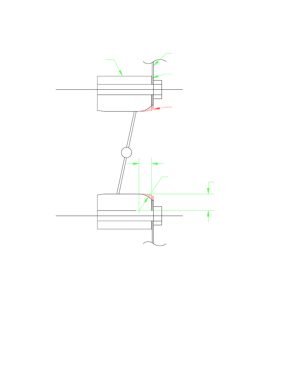
R1/2"

3/8"

1/2"

REMOVE MAT'L

AS SHOWN

GASKET

AIR FILTER

HOUSING

BUTTERFLY

HOUSING


Figure 8 - Butterfly Housing Airflow Improvement 


112

performance other than at wide-open throttle.  Since the ECU senses and corrects for changes in manifold vacuum, no 
tuning changes are required. 


ENLARGED THROTTLE BORES:  AJ6 Engineering (see page 710) offers revised butterfly housings on an exchange 
basis in which the entire bore is enlarged from 2-1/2” to 2-7/8” (32% airflow area increase) and larger butterflies are 
fitted.  Note that their kit includes low-loss foam filters and air filter housings with additional intake openings, fulfilling 
some of the other suggestions above.  The kit also includes an electronic gadget to revise the ECU response, since the 
larger butterflies will have different airflow characteristics than the stock ones relative to throttle position.  AJ6 
Engineering claims a 20-25 horsepower increase with this kit. 

Roger Bywater describes the product: “We produce the large disks ourselves by firstly, cutting blank disks out of brass 
sheet, then, using a special fixture we machine them to exact size and to get the correct closing angle in the enlarged 
throttle bore.  They are not simply turned disks and it is important to get the geometry right so that the correct signal is 
generated across the throttle edge vacuum ports which are themselves critical on size and position.  Boring out the 
throttle bodies exposes a larger diameter portion of the tapping so we install new tapping inserts drilled to produce the 
required vacuum signal from the larger passage. 

“We also machine the spindle slots which otherwise would not accept the larger throttles and we then rebuild the whole 
assembly with new bearings and seals, centralise the disks and adjust to the requisite 0.002" closing gap. 

“The radiused entry which we machine on the throttle body is important to ensure that the throttle bore passes the 
maximum flow by not creating turbulence at the entry point - which is what happens with square edged entry of the 
standard throttles.  We supply a set of specially made gaskets to match the large bore where it joins the manifold and 
also for the larger radiused entry joint to the filter assembly.” 

Chris Carley says, “I bought just the throttle bodies without the filters or cans.  I had to drill out the backs of the filter 
cans to 3-1/8" and also to my surprise had to grind out the tops and sides of the manifolds to match the ID of the throttle 
bodies.  Note the bigger throttles will jam against the standard air filter at wide open - AJ6 & K&N clear though.” 


INTAKE MANIFOLD MODIFICATION:  AJ6 Engineering (page 710) offers an enhancement called the Plus Torque 
Conversion where they cut the intake manifolds open and install little intake horns into the openings into each runner, 
then weld the manifolds back together.  This apparently not only provides a smooth entry into each runner inside the 
manifold, but it also makes all 12 runners the same length -- by making the shorter ones (the middle four) as long as the 
longer ones (the outer two), thereby increasing the Helmholtz resonance benefits for all and enhancing the EFI system’s 
feedback strategy to keep all six cylinders on each bank operating at an optimum fuel/air mixture. 

David Buchner claims that the revised intake manifolds introduced in the early 90’s -- identifiable by the huge “Jaguar 
V12” lettering across the top -- already have the improvements offered in the Plus Torque conversion. 


Other Modifications 


OIL COOLING:  The standard oil cooler on an XJ-S is a “relief” unit, meaning it only cools the oil that doesn’t go 
through the engine.  However, as pointed out by Bob Tilley, the XJ-S sold in Germany is fitted with a “full flow” oil 
cooler system, and the parts are available through Jaguar.  We can make assumptions about why the German cars 
would be different than other cars, possibly involving those Autobahns. 

John Goodman adds, “It’s worth pointing out to others who own later model V12’s who may not be aware that all V12 
HE engines after engine no. 8S44317 had full flow oil cooling, can’t remember the year this was introduced.” 

Both oil systems, as well as almost any other in automotive use, work like this: Oil is drawn from a pickup in the sump 
into the oil pump.  The oil pump is a positive displacement pump, meaning it will move a particular amount of oil for 
each rotation, regardless of how much pressure it has to apply to move it; if something gets plugged up or the oil is 


113

really thick, the oil pressure could skyrocket, blowing seals, pipes, whatever.  So, the oil goes straight from the pump to 
a pressure relief valve, which relieves enough of the oil flow to prevent excessive pressure in the system.  The relieved 
oil goes back to the sump, while the remaining pressurized oil goes through the filter (which has its own relief bypass in 
the event of clogging) and into the galleys that feed the bearings, cam followers, and other parts of the engine requiring 
lubrication. 

In the basic relief oil cooling system in the Jaguar V12, only the oil that is relieved by the pressure relief valve is piped 
to the oil cooler in front of the radiator, and from there back to the intake of the oil pump.  In the full flow system used 
in German cars, the oil destined to go to the galleys is piped to the oil cooler at the front of the radiator and then back to 
the filter head assembly to continue through the filter and into the galleys. 

Physically, the distinction is like this: in the relief system, oil feeds out of the outlet elbow at the bottom front of the 
filter head to the right side of the cooler.  From the left side of the cooler, it goes to a fitting on the bottom front of the 
sandwich plate on the crankcase.  It doesn’t simply return into the sump here, but instead goes directly into the inlet 
elbow on the bottom of the oil pump.  Hence, the oil pump actually draws suction from two places: the sump pickup 
and the return from the cooler. 

The front of the full flow filter head has a pair of fittings that don’t exist on the early style relief filter head and are 
sealed off on later style relief filter heads -- the change probably due to the desire to use the same casting for both relief 
and full flow filter heads.  In the full flow system, oil to the cooler starts at one of these fittings on the filter head itself 
instead of the outlet elbow; the outlet elbow still exists, but the port on the front is sealed off.  The oil feed is piped to 
the right side of the cooler.  From the left side of the cooler, it goes back to the other fitting on the filter head.  The oil 
pump therefore has only one intake, from the pickup in the sump, and the bottom of the sandwich plate either has no 
hole or has a blank-off cover on it. 

The relief system has an inherent shortcoming in that it tends to vary the amount of cooling incorrectly.  When the oil is 
cold, it is also thick, and the pressure relief valve has to relieve a great deal of it in order to limit the pressure.  As a 
result, flow through the cooler is high -- precisely when not needed.  On the other hand, when the oil is hot and thin, 
very little or none at all is relieved, and hence flow through the cooler is minimal -- precisely when it is most needed. 

The full flow system always flows the oil through the cooler before it goes through the engine, so there is always 
cooling.  And, the coolest oil in the system is the oil fed to the galleys, so it can be expected to reduce the incidence of 
burned bearings. 

The relief system has another trait that causes consternation.  In order for a relief valve to work properly, it really needs 
to relieve to a place of zero pressure -- such as directly into the sump.  Because this system relieves through the oil 
cooler, there may be a significant amount of pressure on the back side of the relief valve -- the backpressure caused by 
the flow of thick, cool oil through the tiny passages in the cooler.  The pressure of the oil the engine sees -- and 
therefore the gauge sees -- is the relief pressure of the valve plus the backpressure of the oil cooler.  The backpressure 
of the oil cooler will vary greatly with oil temperature; when cool and thick, the pump will be trying to push a great 
deal of oil through it, but when hot and thin it may see little or no flow at all.  The combination of the viscosity changes 
and the flow changes make for extreme backpressure differences.  As a result, the oil pressure registering on the gauge 
will vary quite a bit more between cold and hot than on most cars.  This doesn’t seem to cause any harm, but it does 
cause owners to get overly concerned. 

If you wish to retrofit the full flow cooling system to a car that came with the relief cooling system, you will need the 
following parts.  The corresponding part numbers for the relief system are also shown: 

 Part Relief 

p/n FF 

p/n 


Oil Suction Pipe 

C35512 

EAC6424 


Oil Suction Elbow 

C33869 

EAC6422 


Oil Suction Elbow Gasket 

C31063 

C31063 


Relief Assembly 

C42796 or EAC7755 

EAC6398 


Relief Outlet Elbow 

C38802 

EAC6789 

 Oil 

Cooler 

C43923 

CBC2692 


Oil Feed Pipe 

EAC1380 

EAC8954 


114


Oil Feed Pipe 

C38074 

CBC2690 


Oil Return Pipe 

C38075 

CBC2691 


Oil Return Pipe 

N/A 

EAC8956 

 Retainer 

N/A 

EAC6413 

 Bracket 

N/A 

EAC6414 


Clamp 

C34608 (1) 

EAC6800 (2) 

 Sleeve 

N/A 

EAC6790 

(2) 

 Bracket 

EAC1381 

EAC6419 

Plus a few bolts, nuts, O-rings, etc., all of which can be purchased locally.  If you’re the industrious type, you can 
probably improvise all those clamps and brackets too. 

You might also be able to avoid buying the relief outlet elbow; you can reuse the old one if you can plug the opening in 
it.  You will have the part that screws into it, oil feed pipe EAC1380, laying around doing nothing if you want to cut the 
fitting off and make a plug out of it. 

The 1987 Parts Catalogue shows the same sandwich plate used for both systems; a square blank-off plate EAC6420 and 
gasket EAC6421 are used to cover the unused hole under the oil pump elbow on cars with full flow cooling.  In all 
probability, later on when all cars were fitted with full flow oil cooling, the sandwich plate was altered to omit the hole. 
 But anyone doing the retrofit is probably going to prefer simply bolting on the blank-off plate to replacing the entire 
sandwich plate.  And they could easily make a blank-off plate and gasket rather than buy them. 

To replace all these parts would require pulling the sump off the engine to replace the oil suction pipe and the oil 
suction elbow.  However, in theory anyway, these replacements may not be necessary, and the retrofit might be 
accomplished without pulling the sump.  The difference in the oil suction elbow is that the one for the relief system has 
the second inlet on it, and this inlet is readily accessible via the opening in the bottom of the sandwich plate.  If this 
second inlet is securely plugged, it will serve the purpose of the EAC6422 part.  This can be done by making a suitable 
part that plugs both the second inlet on the oil suction elbow and the opening in the sandwich plate, or by using a 
separate plug -- perhaps like the rubber expansion-type freeze plugs -- on the suction elbow, along with a simple blank-
off on the sandwich plate.  In fact, the original sump inlet adapter C37882 can be used if you find a way to plug it.  
Going this route would not only reduce disassembly requirements, but it also eliminates the need for purchasing a new 
oil suction pipe, oil suction elbow, and oil suction elbow gasket -- as well as bottom end gaskets you’ll have to replace 
when you open it up. 

Note that the difference in the oil suction pipe -- which is, in fact, the pickup -- is unknown.  But there is no reason to 
believe the one designed for the relief system won’t work properly for the full flow system.  Perhaps the design was 
changed slightly to fit the revised oil suction elbow. 


OIL PRESSURE RELIEF HOSE:  While fiddling with the sandwich plate off, Karl Huff was told by a Jaguar shop that 
“while I'm in there I should replace the oil filter pressure relief hose (?) with a new one from the 6 litre engine.”  This is 
probably referring to the question mark shaped line. 


OIL FILTRATION MODS:  Much of the following was pilfered from an article by Nigel Calder in the March/April 
1994 issue of Ocean Navigator magazine.  It was primarily about auxiliary engines for sailboats, but the issues 
discussed here apply to any piston engine. 

Oil contamination is divided into two categories: chemical and physical contamination. 

Chemical contamination degrades the oil, causing a loss of lubricating properties, and also may introduce substances 
that attack engine parts.  Heat and age can cause oil to oxidize and thicken, encouraging the formation of sludges and 
varnish.  Water can be introduced even in a tight engine by condensation within the crankcase, and causes 
emulsification.  If there happens to be any sulfur in the fuel, some can find its way past the rings and combine with 
water to form sulfuric acid which promptly attacks engine parts.  Unburned fuel coming past the rings also dilutes the 
oil, lowering its viscosity. 


Content   ..  27  28  29  30   ..