содержание .. 192 193 194 195 ..
JAC S5. Обслуживание и эксплуатация - часть 194
SC-10
S5 Service manual
S5 Инструкция по техобслуживанию
Start and Charging System
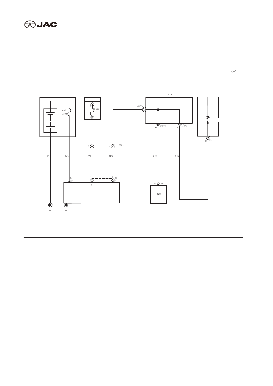
Блок Cхема Пусковой и Зарядной Системы
Schematic Diagram of Charging System
Блок-схема Системы Зарядки
Charging system
Система зарядки
Battery and battery fuse box
Аккумулятор и блок
предохранителей
Outdoor power supply box
Открытый блок питания
Combination meter
Комбинация приборов
Charging
Зарядка
Battery
Батарея
Constant power
Постоянный
источник питания
Electric generator
Электрический генератор
Body ground wire
Заземляющий провод
1. Descriptions of System
1. Описание Системы
Generator supplies DC voltage to vehicle electric system and keeps charging status of battery. Voltage
output is controlled by IC adjuster.
Электрическая система и аккумулятор транспортного средства питается от генератора постоян-
ного тока. Выходное напряжение регулируется регулятором IC.
When ignition switch is turned on, current goes into excitation coil which is excited primarily. After the engine
is started, stator coil begins to generate electricity. Excitation coil is input with current excitation by stator coil.
Port ―B‖ supplies electric to vehicle‘s electric system and charging power supply to battery.
При включении замка зажигания ток поступает в катушку возбуждения. После запуска двигателя
катушка обмотки статора начинает вырабатывать электричество. Катушка возбуждения подклю-
чена к катушке обмотки статора тока возбуждения. Контакт ―B‖ питает электрическую систему и
аккумулятор транспортного средства.
IC adjust will inspect input voltage at port 2 (―S‖ port) and controls output voltage. If excitation current
increases, output electric of AC generator also increases. If excitation current decreases, output electric
also decreases. When battery voltage (voltage at air conditioning generator S port) reaches the adjust-
ing voltage of 14.4V, excitation current is cut off. When battery voltage drops to be lower than adjusting