Ford Focus RS (2011 year). Manual - part 144


  Index      Ford     Ford Focus RS - service repair manual (2011 year) in english


Search            


Content   ..  142  143  144  145   ..


Ford Focus RS (2011 year). Manual - part 144


Front Axle Crossmember Rear Bushing
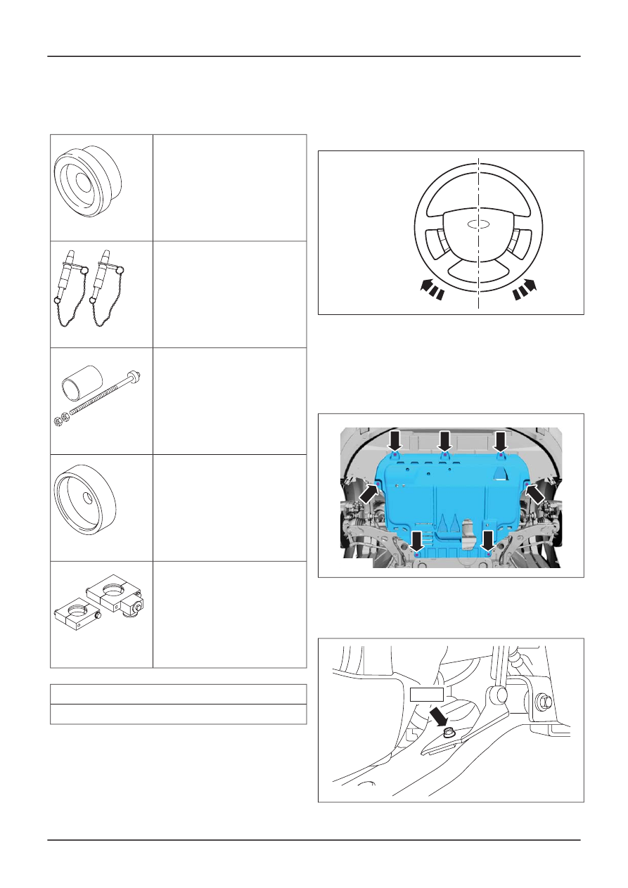
Special Tool(s)

Adapter for 205-071 (Thrust
Pad)
205-071-02

1502651

Alignment Pins, Subframe
205-316 (15-097A)

15097A

Remover/Installer, Pivot
Bushing
205-342

15110

Adapter for 205-342
205-342-02

1511002

Remover/Installer, Subframe
Bush
205-810 Comprises
205-810-01, 205-810-02

E51254

General Equipment

Transmission jack

Securing strap

All vehicles

1. NOTE: Make sure that the road wheels are

in the straight ahead position.

Centralize the steering wheel and lock it in
position.

TIE38834

2. Remove the front wheels and tires.

For additional information, refer to:

Wheel

and Tire

(204-04 Wheels and Tires, Removal

and Installation).

3. Remove the engine undershield.

E40677

4. Detach the headlamp leveling front sensor

bracket from the right-hand lower arm and
secure it to one side (if equipped).

TIE44651

8 Nm

G418578en

502-00-

20

Uni-Body, Subframe and Mounting System

502-00-

20

REMOVAL AND INSTALLATION

5.

CAUTION: Over bending of the exhaust

flexible pipe may cause damage resulting in
failure.

Support the exhaust flexible pipe with a
suitable support wrap or a suitable splint.

TIE0002772

6.

CAUTION: Take care when removing the

exhaust hanger insulators to prevent
damage.

Detach the exhaust flexible pipe from the
exhaust hanger insulators.

TIE39009

All except vehicles with diesel engine

7. Detach the catalytic converter from the

muffler and tailpipe assembly.

• Discard the catalytic converter to muffler and

tailpipe assembly gasket and nuts.

E50598

48 Nm

Vehicles with diesel engine

8. Detach the catalytic converter from the

muffler and tailpipe assembly.

• Discard the catalytic converter to muffler and

tailpipe assembly sealing ring and nuts.

TIE40628

51 Nm

9. Remove the components in the order

indicated in the following illustration(s) and
table(s).

G418578en

502-00-

21

Uni-Body, Subframe and Mounting System

502-00-

21

REMOVAL AND INSTALLATION

E55354

80 Nm

1

2

Description

Item

Engine support insulator front retaining
bolt

1

Front axle crossmember

See Removal Detail
See Installation Detail

2

G418578en

502-00-

22

Uni-Body, Subframe and Mounting System

502-00-

22

REMOVAL AND INSTALLATION

E55353

3

Description

Item

Front axle crossmember rear bushing

See Removal Detail
See Installation Detail

3

10. To install, reverse the removal procedure.

11. Check the toe setting and adjust as

necessary. For additional information, refer
to: (204-00 Suspension System - General
Information)

Specifications

(Specifications),

Front

T

oe Adjustment

(General Procedures).

Removal Details

G418578en

502-00-

23

Uni-Body, Subframe and Mounting System

502-00-

23

REMOVAL AND INSTALLATION

Item 2

Front axle crossmember

NOTE: The front axle crossmember is lowered to
gain access to the front axle crossmember rear
bushings.

1. Detach the steering gear from the front axle

crossmember.

• Using cable ties, support the steering gear.

TIE0036820

2. Using

a transmission jack and a wooden

block,

support the front axle crossmember,

stabilizer bar and lower arm assembly.

3.

W

ARNING: Make sure that the front axle

crossmember is secured to the transmission

jack.

Failure to follow this instruction may

result

in personal injury.

Using

a suitable securing strap, secure the

front

axle crossmember, stabilizer bar and

lower

arm assembly to the transmission jack.

4. Remove the front axle crossmember

retaining bolts (transmission jack shown
removed for clarity).

TIE39071

5. Remove the front axle crossmember bracket

retaining bolts on both sides.

TIE44500

6. Lower the front axle crossmember, stabilizer

bar and lower arm assembly to gain access
to the front axle crossmember rear bushings.

Item 3

Front axle crossmember rear bushing

1. Using the special tools, remove the front axle

crossmember rear bushing.

E52873

205-342

205-071-02

Installation Details

G418578en

502-00-

24

Uni-Body, Subframe and Mounting System

502-00-

24

REMOVAL AND INSTALLATION

Item 3

Front axle crossmember rear bushing

1. Clean the front axle crossmember rear

bushing housing.

2. Using the special tool, attach the front axle

crossmember rear bushing to the front axle
crossmember.

E55447

3. Using the special tools, press the front axle

crossmember rear bushing in approximately
10 mm.

E55811

205-342

205-810

205-342-02

4. Remove the special tool.

E55457

5. Using the special tools, install the front axle

crossmember rear bushing.

E55477

205-342

205-342-02

6. Remove the special tools.

Item 2

Front axle crossmember

1. Using the

transmission jack and the special

tool,

position and align the front axle

crossmember.

1. Insert

the special tool through the front axle

crossmember alignment holes.

2. Slide the locking plates into the groove of the

special tool and tighten the special tool
sleeve.

3. Raise the front axle crossmember engaging

the special tool into the chassis alignment
holes.

TIE0000859

1

3

2

205-316

G418578en

502-00-

25

Uni-Body, Subframe and Mounting System

502-00-

25

REMOVAL AND INSTALLATION

2. Install the front axle crossmember bracket

retaining bolts on both sides.

TIE44501

70 Nm

3.

CAUTION: Make sure that the front axle

crossmember does not move while
tightening the front axle crossmember
retaining bolts.

Install the front axle crossmember retaining
bolts (transmission jack shown removed for
clarity).

TIE39072

115 Nm

275 Nm

4. Remove the special tool.

5. Remove the

securing strap.

6. Lower and

remove the transmission jack

and

the wooden

block.

7. Attach the steering gear to the front axle

crossmember.

• Remove the cable ties.

E0036821

90 Nm

G418578en

502-00-

26

Uni-Body, Subframe and Mounting System

502-00-

26

REMOVAL AND INSTALLATION

Rear Axle Crossmember — Vehicles With: Solid Stabilizer Bar

Link, Vehicles Without: Fuel Additive Tank

General Equipment

Securing strap

Transmission jacks

1. Remove the spring on both sides.
2. Remove the evaporative emission canister

(if equipped).

3. Remove the headlamp leveling rear sensor

(if equipped).

For additional information, refer to:

Exterior Lighting, Removal and
Installation).

4. Detach the headlamp leveling sensor wiring

harness from the rear axle crossmember (if
equipped).

E44185

5. Detach the headlamp leveling sensor wiring

harness from the rear axle crossmember and
disconnect the electrical connector (if
equipped).

E44186

6. Remove the components in the order

indicated in the following illustration(s) and
table(s).

G422315en

502-00-

27

Uni-Body, Subframe and Mounting System

502-00-

27

REMOVAL AND INSTALLATION

Headlamp Leveling Rear Sensor

(417-01


Content   ..  142  143  144  145   ..