Ford Focus RS (2011 year). Manual - part 127


  Index      Ford     Ford Focus RS - service repair manual (2011 year) in english


Search            


Content   ..  125  126  127  128   ..


Ford Focus RS (2011 year). Manual - part 127


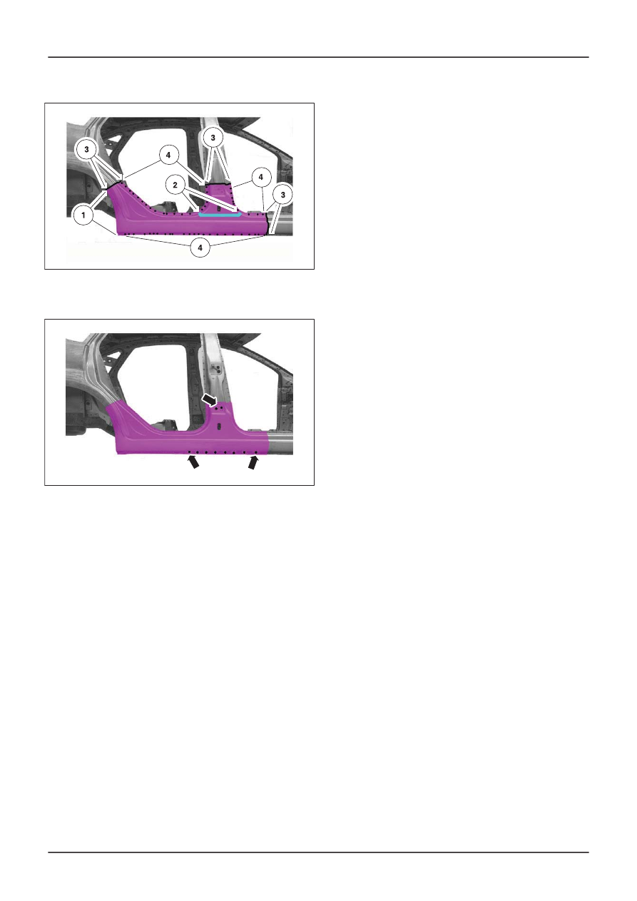
4. Resistance spot weld.

E55359

3. Rocker panel

• Puddle weld.

E55360

G371075en

501-29-

5

Side Panel Sheet Metal Repairs

501-29-

5

REMOVAL AND INSTALLATION

A-Pillar Outer Panel Section and Reinforcement

General Equipment

Measurement and alignment angle system

1. Replacement parts

• A-pillar outer panel
• A-pillar inner panel
• A-pillar reinforcement
• A-pillar/fender apron panel reinforcement

Removal

1. General notes

• The fender apron panel reinforcement is

already removed before commencing the
repair.

• Required removal operations: A-pillar trim

panel, rocker panel trim and driver or
passenger seat.

• Move the carpeting and the wiring away from

the working area.

2. A-pillar/fender apron panel reinforcement

• Mill out the spot welds.

E56215

NOTE: To gain access to the front area of the
B-pillar inner panel, the separating cut on the outer
rocker panel must be made according to the
specified dimensions (550 mm).

3. Outer A-pillar

1. Cut point.
2. Mill out the spot welds.

3. Mill out the spot welds (two panel

thicknesses).

E56216

550 mm

4. A-pillar reinforcement

1. Mill out the spot welds.
2. Heat the area (approx. 170°) and detach the

NVH element.

E56217

5. NOTE: To gain access to the original A-pillar

inner panel join, the B-pillar inner panel must
be cut at the front and removed. The part cut
away will be re-used for the installation.

B-pillar inner panel

G427333en

501-29-

6

Side Panel Sheet Metal Repairs

501-29-

6

REMOVAL AND INSTALLATION

1. Cut point.
2. Mill out the spot welds.

6. Inner A-pillar

1. Cut point.
2. Mill out the spot welds.
3. Mill out the spot welds (two panel

thicknesses).

Installation

NOTE: Before resistance spot welding of body
panels with a total panel thickness of 3 mm and
greater, the welding equipment instructions
contained in sub-section 501-25 must be followed.

1. Inner A-pillar

1. Continuous MIG weld.
2. Resistance spot weld.

2. A-pillar reinforcement

• Drill holes for puddle welding (diameter: 10

mm).

3. NOTE: Only tack-weld A-pillar reinforcement.

The final weld joint is made with the outer
A-pillar installed. The puddle weld areas
(item 2) on the A-pillar reinforcement must
be ground down, otherwise the outer A-pillar
cannot be inserted correctly.

A-pillar reinforcement

G427333en

501-29-

7

Side Panel Sheet Metal Repairs

501-29-

7

REMOVAL AND INSTALLATION

1. Apply PU glass adhesive to the NVH

element.

2. Puddle weld.
3. Resistance spot weld.

E56223

4. NOTE: The puddle weld areas on the B-pillar

inner panel must be ground down, otherwise
it cannot be installed using resistance spot
welding.

B-pillar inner panel

• Puddle weld.

E56222

5. B-pillar inner panel

1. Continuous MIG weld.
2. Puddle weld.
3. Resistance spot weld.

E56240

6. Outer A-pillar

• Drill holes for puddle welding (diameter: 10

mm).

E56224

7. Outer A-pillar

1. Continuous MIG weld.
2. Puddle weld.
3. Resistance spot weld.

E56225

8. NOTE: Only tack-weld A-pillar/fender apron

panel reinforcement. The final welded joint
is made with the fender panel reinforcement
installed.

A-pillar/fender apron panel reinforcement

G427333en

501-29-

8

Side Panel Sheet Metal Repairs

501-29-

8

REMOVAL AND INSTALLATION

• Resistance spot weld.

E56226

G427333en

501-29-

9

Side Panel Sheet Metal Repairs

501-29-

9

REMOVAL AND INSTALLATION

B-Pillar and Reinforcement — 3-Door

General Equipment

Measurement and alignment angle system

1. Replacement parts

• B-pillar inner panel
• B-pillar reinforcement

Removal

1. General notes

• Necessary removal work: Front door, B-pillar

trim panel, rocker panel trim, headliner, front
and rear seats.

• Fold back the carpets and move the wiring

harness out of the working area.

2. NOTE: If the B-pillar inner panel is also being

renewed, the cut on the upper B-pillar must
be made according to dimensions.
Depending on the damage, it is also possible
to carry out a partial replacement of the
B-pillar reinforcement.

B-pillar reinforcement

1. Cut point.
2. Mill out the spot welds.
3. Mill out the spot weld and drill out to 10 mm.

4. Cut location for partial replacement.

E56463

95 mm

3. Inner B-pillar

1. Cut locations.
2. Mill out the spot welds.

G450967en

501-29-

10

Side Panel Sheet Metal Repairs

501-29-

10

REMOVAL AND INSTALLATION

3. Rough cut location.

E56464

155 mm

130 mm

4. NOTE: The spot welds at pos. 1 only join the

rear panel layers.

Inner B-pillar

1. Mill out the spot welds from the rear using

the spherical milling cutter.

2. Mill out the spot welds (three panel

thicknesses).

E56465

Installation

NOTE: Before resistance spot welding of body
panels with a total panel thickness of 3 mm and

greater, the welding equipment instructions
contained in sub-section 501-25 must be followed.

1. Inner B-pillar

• Drill holes for puddle welding (two panel

thicknesses).

E56466

2. NOTE: Only tack-weld the B-pillar inner panel

to the lower rocker panel. The final weld joint
is made with the B-pillar reinforcement and
quarter panel installed.

Inner B-pillar

1. Continuous MIG weld.
2. Puddle weld.
3. Resistance spot weld.

E56467

G450967en

501-29-

11

Side Panel Sheet Metal Repairs

501-29-

11

REMOVAL AND INSTALLATION

3. NOTE: Only tack-weld the B-pillar

reinforcement in the areas of the door and
side window cut-out and the lower rocker
panel. The final welded joint is made with the
quarter panel installed.

B-pillar reinforcement

1. Continuous MIG weld.
2. Puddle weld.
3. Resistance spot weld.

E56468

G450967en

501-29-

12

Side Panel Sheet Metal Repairs

501-29-

12

REMOVAL AND INSTALLATION


Content   ..  125  126  127  128   ..