Ford Focus RS (2011 year). Manual - part 121
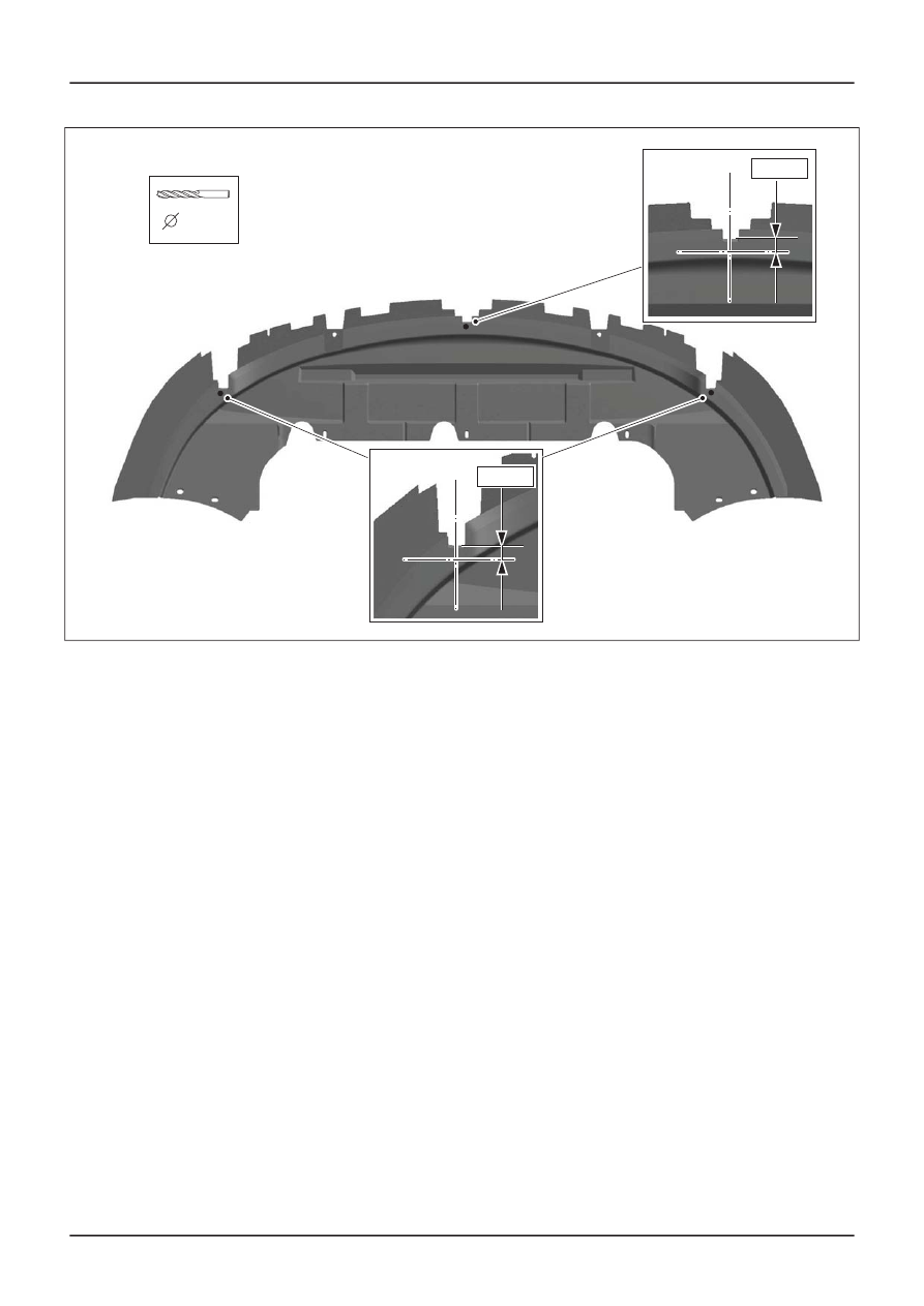
E116815
8,5mm
10 mm
10 mm
G1202520en
501-26-
33
and Tolerance Checks
501-26-
33
DESCRIPTION AND OPERATION
|
|
|
E116815 8,5mm 10 mm 10 mm G1202520en 501-26- 33 and Tolerance Checks 501-26- 33 DESCRIPTION AND OPERATION |