Ford Focus RS (2011 year). Manual - part 103
Restraints Control Module (RCM)
General Equipment
Worldwide diagnostic system (WDS)
WARNINGS:
To avoid accidental deployment, the
restraints control module (RCM) backup
power supply must be depleted. Wait at
least one minute after disconnecting the
battery ground cable(s) before
commencing any repair or adjustment to
the supplemental restraint system (SRS),
or any component(s) adjacent to the SRS
sensors. Failure to follow these
instructions may result in personal injury.
To minimize the possibility of premature
deployment, do not use radio key code
savers when working on the supplemental
restraint system. Failure to follow this
instruction may result in personal injury.
Never probe the electrical connectors of
air bag modules or any other supplemental
restraint system component. Failure to
follow this instruction may result in
personal injury.
1. Disconnect the battery ground cable.
Mounting and Cables, General Procedures).
2. Remove the floor console. For additional
information, refer to:
Console, Removal and Installation),
Instrument Panel and Console, Removal
and Installation).
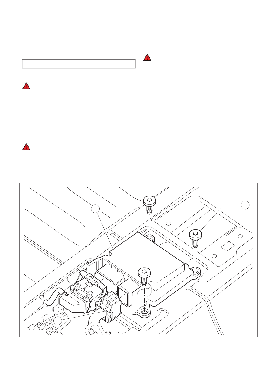
3. Remove the components in the order
indicated in the following illustration(s) and
table(s).
TIE39632
3
1
10 Nm
2
G296347en
501-20B-
128
Supplemental Restraint System
501-20B-
128
REMOVAL AND INSTALLATION
For additional information, refer to:
Battery
Disconnect and Connect
(414-01 Battery,
Floor Console
(501-12 Instrument Panel and
Floor Console - Vehicles Built From: 03/2007,
Vehicles With
:
Center Armrest
(501-12