Ford Focus RS (2011 year). Manual - part 95
DETAILS/RESULTS/ACTIONS
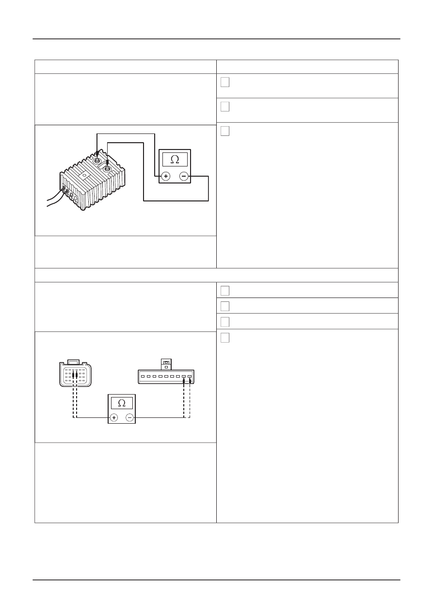
TEST CONDITIONS
2 Select DMM specific on the Ford approved
diagnostic tool.
3 Connect the test and deployment lead to the
Ford approved diagnostic tool.
4 Measure the resistance of the driver air bag
module squib.
• Is the resistance between 2 and 3 ohms?
ൺ
Yes
TIE39388
REPEAT the self-test, CLEAR the DTCs.
REACTIVATE the system.
ൺ
No
INSTALL a new driver air bag module.
Supplemental Restraint System, Removal
and Installation).
REPEAT the self-test, CLEAR the DTCs.
REACTIVATE the system.
AF3: CHECK THE CLOCKSPRING FOR OPEN CIRCUIT OR HIGH RESISTANCE
1 Ignition switch in position 0.
2 Disconnect RCM C426.
3 Disconnect Clockspring C896.
4 Measure the resistance between the:
• RCM C426 pin 3, circuit 15S-JA8 (GN/RD),
harness side and the clockspring C896 pin 1,
circuit 15S-JA8 (GN/RD), harness side.
• RCM C426 pin 4, circuit 91S-JA8 (BK/OG),
harness side and the clockspring C896 pin 2,
circuit 91S-JA8 (BK/OG), harness side.
TIE0036499
• Are the resistances less than 5 ohms?
ൺ
Yes
Install a new clockspring.
Restraint System, Removal and Installation).
REPEAT the self-test, CLEAR the DTCs.
REACTIVATE the system.
ൺ
No
REPAIR circuit 15S-JA8 (GN/RD) or circuit
91S-JA8 (BK/OG). REPEAT the self-test,
CLEAR the DTCs. REACTIVATE the system.
G401865en
501-20B-
64
Supplemental Restraint System
501-20B-
64
DIAGNOSIS AND TESTING
REFER to:
Driver Air Bag Module
(501-20
REFER to:
Clockspring
(501-20 Supplemental