Ford Focus RS (2011 year). Manual - part 91
DETAILS/RESULTS/ACTIONS
TEST CONDITIONS
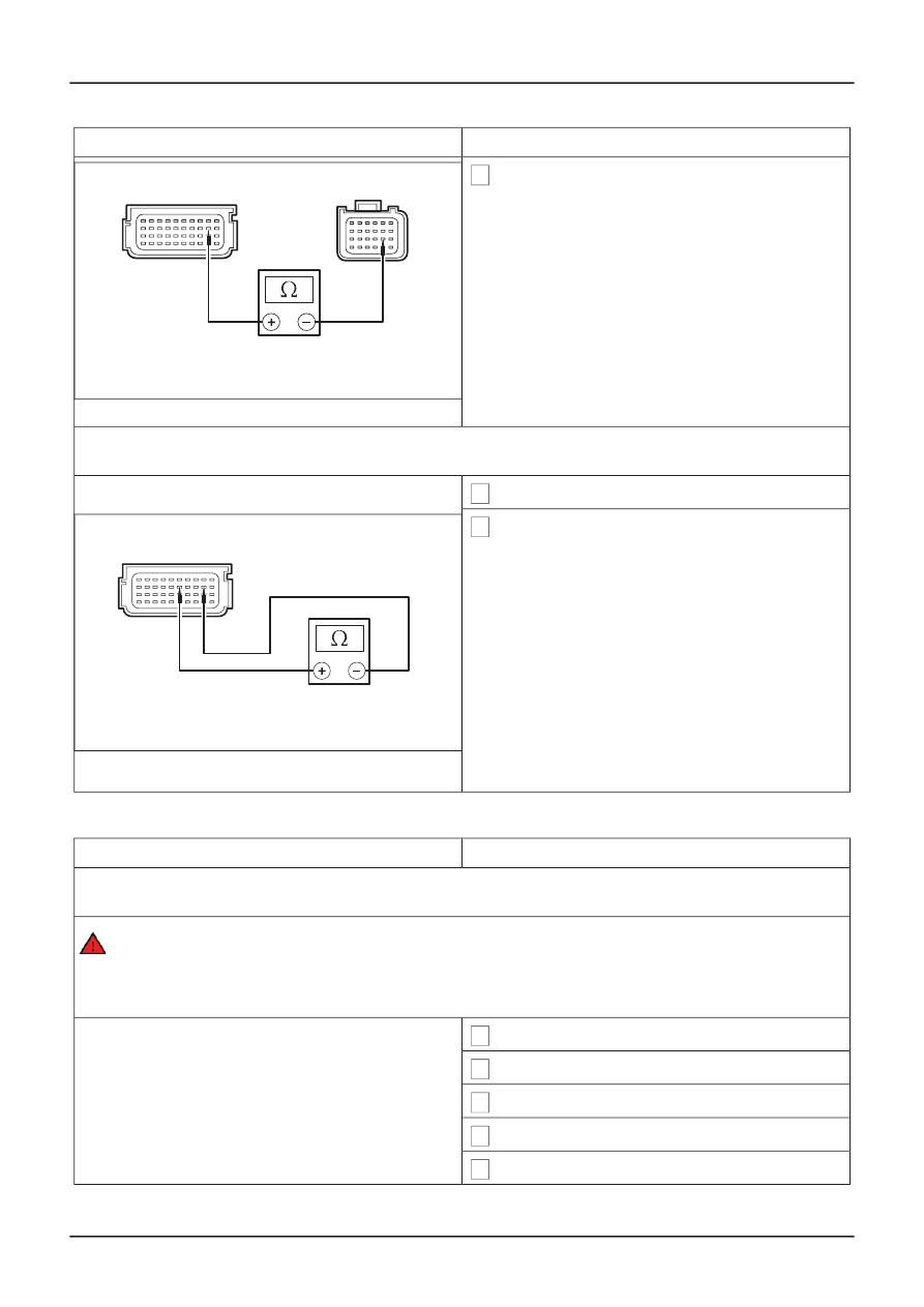
6 Measure the resistance between the RCM C426
pin 14, circuit 8-JA49 (WH), harness side and
the RCM C429 pin 29, circuit 8-JA40 (WH/VT),
harness side.
• Is the resistance greater than 10,000 ohms?
ൺ
Yes
E64840
ൺ
No
REPAIR circuit 8-JA40 (WH/VT) and circuit 8-
JA49 (WH). REPEAT the self-test, CLEAR the
DTCs. REACTIVATE the system.
G2: CHECK FOR A CROSS LINK BETWEEN THE DRIVER SIDE IMPACT SENSOR CIRCUIT AND
THE PASSENGER SIDE IMPACT SENSOR CIRCUIT
1 Disconnect Driver Side Impact Sensor C427.
2 Measure the resistance between the RCM C429
pin 26, circuit 8-JA39 (WH), harness side and
the RCM C429 pin 29, circuit 8-JA40 (WH/VT),
harness side.
• Is the resistance greater than 10,000 ohms?
ൺ
Yes
E64734
REPEAT the self-test, CLEAR the DTCs.
REACTIVATE the system.
ൺ
No
REPAIR circuit 8-JA39 (WH) and circuit 8-
JA40 (WH/VT). REPEAT the self-test, CLEAR
the DTCs. REACTIVATE the system.
PINPOINT TEST H : DTC B104D: FRONT CRASH SENSOR CROSS LINK TO ANOTHER SENSOR
DETAILS/RESULTS/ACTIONS
TEST CONDITIONS
H1: CHECK FOR A CROSS LINK BETWEEN THE CRASH SENSOR AND THE DRIVER SIDE IMPACT
SENSOR
WARNING: To avoid accidental deployment, the RCM backup power supply must be depleted.
Wait at least one minute after disconnecting the battery ground cable(s) before commencing
any repair or adjustment to the SRS, or any component(s) adjacent to the SRS sensors.
Failure to follow these instructions may result in personal injury.
1 Deactivate the SRS.
2 Disconnect RCM C426.
3 Disconnect RCM C429.
4 Disconnect Crash Sensor C420.
5 Disconnect Driver Side Impact Sensor C427.
G401865en
501-20B-
32
Supplemental Restraint System
501-20B-
32
DIAGNOSIS AND TESTING
GO to G2.