Ford Orion. Manual - part 60


  Index      Ford     Ford Orion - service and repair manual


Search            


Content   ..  58  59  60  61   ..


Ford Orion. Manual - part 60


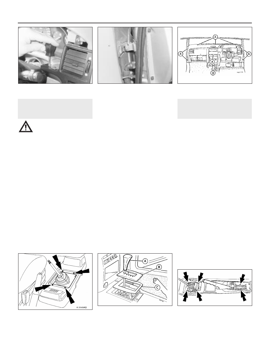
36.6  Long centre console retaining nut

and screw locations (arrowed) - automatic

transmission console shown

35 Facia 

removal and refitting

4

Warning: On vehicles fitted with a
passenger’s air bag, seek the
advice of a Ford dealer

concerning safety implications when
removing the facia assembly.

Removal

Disconnect the battery negative (earth) lead
(refer to Chapter 5, Section 1).
Refer to Chapter 10 for details, and remove
the steering wheel.
Undo the two upper and four lower
retaining screws, and remove the upper and
lower steering column shrouds.
Refer to the appropriate Chapters
concerned for details, and remove the
following facia-associated items:
a)

Steering column multi-function switch
(Chapter 12).

b)

Instrument panel (Chapter 12).

c)

Choke cable (Chapter 4).

d)

Heating/ventilation controls and control
panel (Chapter 3).

e)

Cigar lighter and ashtray (Chapter 12).

f)

Radio/cassette player (Chapter 12).

g)

Clock (Chapter 12).

Undo the two retaining screws, and remove
the side vent panel from the facia on the
driver’s side. As it is withdrawn, disconnect

any wiring connections from the panel-
mounted switches (see illustration).
Undo the two hinge/retaining screws
securing the glovebox lid, and remove it. Undo
the two catch screws, and remove the lock/
catch. As the catch is withdrawn, disconnect
the bulbholder/switch wiring connector.
Where fitted, detach and remove the
footwell lights from the driver and passenger
side lower facia (Chapter 12).
Pull free the weatherstrip from the leading
edge of the door aperture each side to gain
access to the outboard mounting screws.
Unscrew and remove the retaining screws
from the points indicated (see illustrations).
Withdraw the facia from its mounting. As it
is withdrawn, note the routing of the cables
attached to the facia, then detach the 
cable ties and remove the facia from the
vehicle.
10 The associated components of the facia
can (if required) be detached by undoing the
appropriate retaining screws.

Refitting

11 Refitting is a reversal of the removal
procedure. Ensure that all wiring and cables
are correctly routed and securely
reconnected. Refer to the appropriate
Chapters for details on refitting the associated
fittings to the facia panel.
12 When the facia panel is completely refitted,
reconnect the battery then test the various
facia and steering column switches to ensure
that they operate in a satisfactory manner.

36 Centre console 

removal and refitting

1

Removal

Short console (manual transmission)

Unscrew and remove the knob from the
gear lever, then prise free the lever gaiter and
bezel. Slide the gaiter and bezel up the lever,
and lift them off.
Unscrew the four retaining screws, and
remove the console (see illustration).

Long console (manual and automatic
transmission)

On manual transmission models, Unscrew
and remove the knob from the gear lever, then
prise free the lever gaiter and bezel. Slide the
gaiter and bezel up the lever, and lift them off.
On automatic transmission models, select
“P” (Park). Unscrew and remove the knob
from the lever, then prise free the lever
indicator panel, followed by the bezel (see
illustration)
.
On vehicles with electric windows or an
electrically-operated luggage compartment
lock, carefully prise out the switch panel or
switch, and disconnect the wiring connectors.
Undo the four console retaining nuts and
two screws (see illustration).
Pull up the handbrake lever as far as
possible, and manipulate the console over the
handbrake lever and gear lever. If insufficient
clearance exists, slacken the handbrake
adjuster as described in Chapter 1.

11•20 Bodywork and fittings

36.4  Automatic transmission selector

lever knob (A), lever indicator panel (B) and

panel bezel (C)

36.2  Short centre console retaining screw

locations (arrowed)

35.8B  Facia retaining screw locations “A”

(screw only) and “B” (screw and washers)

35.8A  Pull free the weatherstrip for access

to the outboard facia screws

35.5  Side vent panel removal on the

driver’s side

Refitting

Refitting is a reversal of removal. If it was
necessary to slacken the handbrake adjust-
ment for removal of the console, re-check the
adjustment as described in Chapter 1.

37 Wheel arch liners 

removal and refitting

1

Removal

Apply the handbrake, then loosen off the
front roadwheel nuts on the side concerned.
Raise the vehicle at the front end, and support
it on axle stands. Remove the roadwheel.
Unscrew and remove the seven Torx-type
retaining screws (see illustration).
Press the liner inwards at the top to
disengage it from the locating tang (see
illustration)
, then withdraw it from the vehicle.

Refitting

Refit in the reverse order of the removal
procedure. Tighten the roadwheel nuts to the
specified torque wrench setting.

38 Radiator grille 

removal and refitting

1

Removal

Pre-1993 models

Raise and support the bonnet. Unscrew
and remove the four retaining screws along
the top edge of the grille, then carefully lift the

grille free, and disengage it from the locating
socket each side at the bottom (see
illustration)
.

1993-on models

Raise and support the bonnet. Undo the
three nuts securing the grille to the inside of
the bonnet, and lift off the grille.

Refitting

Refit in the reverse order of the removal
procedure.

39 Powered hood 

(Cabriolet models) 
removal and refitting

3

Note:  The following manuals detail the
removal and refitting of the hood cover only.
The removal, repair and refitting of the hood
frame, insulation and headlining are specialised
tasks, and must be entrusted to a Ford garage
or an automotive upholstery specialist.

Removal

Open the roof, then remove the rear seat
cushion by prising free the blanking plugs and
unscrewing the seat hinge screw each side.
Remove the rear quarter trim panel as
described in Section 34.
Raise the roof just enough the allow access
to the rear parcel shelf.
Disconnect the spring wire rod from the
retainer on each side (see illustration).
Unscrew and remove the spring wire
securing screw on each side.
Disconnect the spring wire from the
housing at the other end on each side.

Detach the wiring from the heated rear
window connectors.
Unscrew and remove the two hinge damper
bolts on each side (see illustration), then fully
open the roof.
Prise free the hydraulic rod securing clip,
then unscrew and remove the three retaining
bolts from the brackets (see illustration).
10 Enlist the aid of an assistant to help in
removing the roof assembly from the car. Grip
the roof and pull it towards the front to release
it at the rear end, then carefully lift clear of the
car.

Refitting

11 Refitting is a reversal of the removal
procedure. When the roof assembly is fully
reconnected, check that it operates in a
satisfactory manner before refitting the rear
quarter panel and seat cushion.

40 Powered hood control

system - hose removal,
refitting and system bleeding

3

Hose removal

Open the boot lid and lower the hood.
Remove the appropriate trim panels to gain
access to the pump (in the left-hand side of
the luggage area) and the hydraulic ram
(located behind the rear quarter panel) on the
side concerned.
Where more than one hose is to be detached
from the pump, the respective hoses and their
connections to the pump should be labelled
and marked for correct identification, to avoid

Bodywork and fittings  11•21

37.3  Disengaging the wheel arch liner

from the locating tang

37.2  Wheel arch liner retaining screw

locations (arrowed)

39.8  Cabriolet powered hood hinge

damper (arrowed)

39.4  Cabriolet powered hood spring wire

rod retainers

38.1  Radiator (front) grille panel retaining

screw removal - pre-1993 models

11

39.9  Cabriolet powered hood hydraulic rod

A   Securing clip        B   Retaining bolts

the possibility of confusion when reconnecting
them (see illustrations).
Loosen off the fluid filler plug on the pump
to depressurise the system.
Disconnect the hose(s) from the location
tangs to the body, and the tape securing it to
the ram and other hoses. Loosen off the hose-
to-pump union(s), and detach the hose(s).
Note that it may well be necessary to detach
and partially remove the pump as described in
Section 42 to enable a hose on the left-hand
side of the pump to be disconnected. Catch
any spillage of hydraulic fluid in a suitable
container, and plug the hose(s)/connection(s)
to prevent the ingress of dirt. Note that the
hood must not be raised whilst the hydraulic
lines are disconnected, or hydraulic fluid
remaining in the system will be ejected

Hose refitting

Refitting is a reversal of the removal pro-
cedure. When the hoses are reconnected, top-
up and bleed the hydraulic system as follows.

System bleeding

Remove the fluid filler plug from the pump.
Top-up the fluid level with the specified fluid
type (see Specifications) to the “MAX” mark,
then loosely retighten the plug. Unscrew and
open the by-pass tap 90 to 180º (maximum),
then manually raise and lower the hood once.
Recheck the fluid level in the pump, top-up

the level if required, tighten the by-pass tap
and refit the filler plug (see illustration).
Turn the ignition switch to position “I”
(accessory), then close and open the roof five
times using the roof operating switch. At the
end of this cycle, the roof should operate
smoothly in each direction, and the pump
motor should have a constant operating sound.
With the roof in the open position, recheck
the hydraulic fluid level in the pump, and top-
up if required.

41 Powered hood control

damper/hydraulic ram -
removal and refitting

3

Removal

Lower the hood, then detach and remove
the left-hand trim panel in the luggage area to
gain access to the hydraulic pump.
Depressurise the hydraulic system by
loosening off the pump hydraulic fluid filler plug.
Remove the rear quarter trim panel from the
side concerned, as described in Section 34.
Label the hoses and their connections to
the hydraulic ram, to identify them for refitting
(see illustration).
Release the circlips securing the ram at
each end to its attachment points to the
vehicle. Note that the lower securing point has
the larger of the circlips.
Loosen off the hydraulic hose union
connectors to the ram, withdraw the ram from

its mounting points, and hold it and the
hydraulic connections over a suitable
container. Detach the hydraulic hoses, and
drain all of the fluid into the container before
removing the ram. Use plugs to seal off the
hoses and the hydraulic connections to the
ram, so preventing the ingress of dirt and any
further fluid leakage. Note that the hood must
not be raised whilst the hydraulic lines are
disconnected, or hydraulic fluid remaining in
the system will be ejected.

Refitting

Refitting is a reversal of the removal
procedure. When the ram is refitted to its
mountings and the hoses are reconnected to it,
top-up and bleed the hydraulic system as
described in the previous Section, before
refitting the quarter trim panel (Section 34) and
the pump cover/side trim in the luggage area.

42 Powered hood operating

motor and pump 
removal and refitting

3

Removal

Disconnect the battery negative (earth) lead
(refer to Chapter 5, Section 1).
Open the boot lid, then detach and remove
the left-hand side trim in the luggage area for
access to the pump/motor.
Unscrew the by-pass tap 90 to 180º (see
illustration 40.6).
Lower the roof manually, then allow any
residual pressure in the system to escape by
loosening the filler plug on the top of the pump.
Retighten the filler plug and tap. Detach the
wiring connector to the pump motor.
Label the respective hoses and their
connections to the pump for correct identifi-
cation prior to detaching them, to avoid any
possibility of confusion when reconnecting
them (see illustration 40.2A).
Undo the pump retaining nuts, then partially
withdraw the pump. Locate a suitable
container (or some rags) beneath it, then
unscrew the hydraulic hose unions and
detach the hoses from the pump. Plug the
exposed ends of the pump and hoses, to
prevent the ingress of dirt and further fluid
leakage. Remove the pump. Note that the
hood must not be raised whilst the hydraulic
lines and pump are disconnected, or hydraulic
fluid remaining in the system will be ejected.

Refitting

Ensure that the hose connections are clean,
then reconnect the hoses to the pump, hand-
tightening them at this stage.
Reconnect the pump motor wiring
connection, relocate the pump into position,
and tighten its retaining nuts. Check that the
hoses are not distorted or under undue
tension, then fully tighten their unions.
10 Top-up the pump with the specified
hydraulic fluid, and bleed the system as
described in Section 40.
11 Reconnect the battery earth lead.

11•22 Bodywork and fittings

41.4  Cabriolet powered hood hydraulic

ram hose connections, showing the 

upper (A) and lower (B) mounting circlips

40.6  Cabriolet powered hood hydraulic

pump

A

Filler plug

B By-pass tap
C Fluid level MAX mark

40.2B  Cabriolet powered hood operating

components and hydraulic hose routings

A

Hydraulic pump

B Hydraulic ram (left-hand side)
C Hydraulic ram (right-hand side)

40.2A  Hydraulic hose connections to the

powered hood pump unit

A

Filler plug

B Hose unions and markings
C Pump multi-plug
D Pump mounting

12

Fuses (in vehicle fusebox)

Note: Fuse ratings and circuits are liable to change from year to year. Consult the handbook supplied with the vehicle, or consult a Ford dealer,
for specific information.

Chapter 12
Body electrical system

Air bag clock spring - removal and refitting  . . . . . . . . . . . . . . . . . . . 29
Air bag control module - removal and refitting  . . . . . . . . . . . . . . . . . 28
Air bag (driver’s side) - removal and refitting  . . . . . . . . . . . . . . . . . . 27
Anti-theft system components - removal and refitting  . . . . . . . . . . . 26
Anti-theft systems - general information . . . . . . . . . . . . . . . . . . . . . . 25
Auxiliary warning system - general information and

component renewal . . . . . . . . . . . . . . . . . . . . . . . . . . . . . . . . . . . . 30

Battery - check, maintenance and charging  . . . . . . . .

See Chapter 1

Battery - removal and refitting  . . . . . . . . . . . . . . . . . . .

See Chapter 5

Bulbs (exterior lights) - renewal . . . . . . . . . . . . . . . . . . . . . . . . . . . . .

5

Bulbs (interior lights) - renewal  . . . . . . . . . . . . . . . . . . . . . . . . . . . . .

6

Cigar lighter - removal and refitting . . . . . . . . . . . . . . . . . . . . . . . . . . 12
Clock - removal and refitting . . . . . . . . . . . . . . . . . . . . . . . . . . . . . . . 13
Compact disc player - removal and refitting . . . . . . . . . . . . . . . . . . . 21
Electrical fault-finding - general information  . . . . . . . . . . . . . . . . . . .

2

Electrical system check  . . . . . . . . . . . . . . . . . . . . . . . .

See Chapter 1

Exterior light units - removal and refitting  . . . . . . . . . . . . . . . . . . . . .

7

Fuses and relays - general information  . . . . . . . . . . . . . . . . . . . . . . .

3

General information . . . . . . . . . . . . . . . . . . . . . . . . . . . . . . . . . . . . . .

1

Headlight beam alignment - checking and adjustment  . . . . . . . . . .

8

Horn - removal and refitting  . . . . . . . . . . . . . . . . . . . . . . . . . . . . . . . 14
Instrument panel - removal and refitting  . . . . . . . . . . . . . . . . . . . . . .

9

Instrument panel components - removal and refitting  . . . . . . . . . . . 10
Power amplifier - removal and refitting  . . . . . . . . . . . . . . . . . . . . . . . 24
Radio aerial - removal and refitting  . . . . . . . . . . . . . . . . . . . . . . . . . . 23
Radio/cassette player - removal and refitting  . . . . . . . . . . . . . . . . . . 20
Speakers - removal and refitting  . . . . . . . . . . . . . . . . . . . . . . . . . . . . 22
Speedometer cable - removal and refitting . . . . . . . . . . . . . . . . . . . . 11
Switches - removal and refitting  . . . . . . . . . . . . . . . . . . . . . . . . . . . .

4

Tailgate wiper motor assembly - removal and refitting  . . . . . . . . . . . 18
Windscreen wiper motor and linkage - removal and refitting  . . . . . . 16
Windscreen wiper pivot shaft - removal and refitting  . . . . . . . . . . . . 17
Windscreen/tailgate washer system components - removal

and refitting  . . . . . . . . . . . . . . . . . . . . . . . . . . . . . . . . . . . . . . . . . . 19

Windscreen/tailgate washer system and wiper 

blade check  . . . . . . . . . . . . . . . . . . . . . . . . . . . . . . .

See Chapter 1

Wiper arms - removal and refitting  . . . . . . . . . . . . . . . . . . . . . . . . . . 15

12•1

Easy, suitable for
novice with little
experience

Fairly easy, suitable
for beginner with
some experience

Fairly difficult,
suitable for competent
DIY mechanic

Difficult, suitable for
experienced  DIY
mechanic

Very difficult,
suitable for expert
DIY or  professional

Degrees of difficulty

Specifications

Contents

No

Rating 

(amps)

Circuit(s) protected

1

25  . . . . . Heated rear window, adjustable door mirrors

2

30  . . . . . Anti-lock braking system

3

10  . . . . . Oxygen sensor

4

15  . . . . . Right-hand main beam, right-hand auxiliary light

5

20  . . . . . Fuel pump

6

10  . . . . . Right-hand sidelight

7

10  . . . . . Left-hand sidelight

8

10  . . . . . Rear foglight

9

30  . . . . . Radiator cooling fan

10

10  . . . . . Left-hand dip beam

11

15  . . . . . Front foglights

12

10  . . . . . Direction indicator, reversing lights

13

20  . . . . . Wiper motor, washer pump

14

20  . . . . . Heater blower

15

30  . . . . . Anti-lock braking system

16

3  . . . . . . Heated windscreen

No

Rating 

(amps)

Circuit(s) protected

17

-  . . . . . . Spare

18

15  . . . . . Left-hand main beam, left-hand auxiliary light

19*

20  . . . . . Central locking system, anti- theft alarm, electric   

door mirrors

19**

3  . . . . . . ABS module

20

15  . . . . . Horn

21

15  . . . . . Interior lights, clock, radio, cigar lighter

22

30  . . . . . Electric windows

23

30  . . . . . Headlight washer system

24

10  . . . . . Right-hand dip beam

25

3  . . . . . . EEC IV engine management system

26

5  . . . . . . Heated front seats

27

10  . . . . . Brake stop-lights

28

10  . . . . . Air conditioning system

29**

20  . . . . . Central locking system, anti-theft alarm

Early models   ** Later models


Content   ..  58  59  60  61   ..