Ford Orion. Manual - part 10


  Index      Ford     Ford Orion - service and repair manual


Search            


Content   ..  8  9  10  11   ..


Ford Orion. Manual - part 10


rear end of the rocker shaft is to the same side
as the rocker arm adjusting screws (closest to
the thermostat end of the cylinder head when
fitted) (see illustration). This is essential for
the correct lubrication of the cylinder head
components.
Refit the rocker shaft assembly. As it is
fitted, ensure that the rocker adjuster screws
engage with their corresponding pushrods.
10 Refit the rocker shaft retaining bolts,
hand-tighten them and then tighten them to
the specified torque wrench setting. As they
are tightened, some of the rocker arms will
apply pressure to the ends of the valve stems,
and some of the rocker pedestals will not
initially be in contact with the cylinder head -
these should pull down as the bolts are
tightened to their specified torque. If for any
reason they do not, avoid the temptation to
overtighten in order to pull them into position;
loosen off the bolts, and check the cause of
the problem. It may be that the rocker adjuster
screws require loosening off in order to allow
the assembly to be tightened down as
required.
11 Adjust the valve clearances as described
in Section 6.

10 Cylinder head 

removal and refitting

3

Removal

On CFi-equipped engines, depressurise the
fuel system as described in Chapter 4.
Disconnect the battery negative (earth) lead
(refer to Chapter 5, Section 1).
Whenever you disconnect any vacuum
lines, coolant or emissions hoses, wiring loom
connectors, earth straps and fuel lines as part
of the following procedure, always label them
clearly, so that they can be correctly
reassembled. Masking tape and/or a touch-
up paint applicator work well for marking
items. Take instant photos, or sketch the
locations of components and brackets.
Refer to Section 5 and remove the rocker
cover.
Refer to Chapter 1 and drain the cooling
system.
Disconnect the hoses from the thermostat
housing.

Disconnect the heater (coolant) hoses from
the inlet manifold and CFi unit, where applicable.
Disconnect the accelerator and choke
cables from the carburettor or CFi unit, as
applicable (see Chapter 4).
Disconnect the fuel and vacuum hoses
from the carburettor/CFi unit and inlet
manifold.
10 Disconnect the HT leads from the spark
plugs and the support bracket. Unscrew and
remove the spark plugs.
11 Disconnect the electrical leads from the
temperature gauge sender, radiator cooling
fan, the engine coolant temperature sender
(beneath the inlet manifold), the radio earth
lead on the inlet manifold, and the anti-run-on
(anti-dieselling) valve at the carburettor.
12 Remove the engine oil filler cap and
breather hose.
13 On vehicles equipped with a pulse-air
system, remove the pulse-air piping as
described in Chapter 6.
14 Apply the handbrake, then raise the
vehicle at the front end, and support it on axle
stands.
15 Undo the retaining nuts and bolts, and
disconnect the exhaust downpipe from the
manifold. Remove the flange gasket. (Note
that both the gasket and the joint self-locking
nuts must be renewed.) To prevent the
exhaust system from being strained, tie the
downpipe up using strong wire or a length of
cord to support it. On catalytic converter-
equipped vehicles, take care not to stretch the
oxygen sensor wiring, where applicable; if
necessary, disconnect the sensor’s multi-
plug. Lower the vehicle.

16 Undo the four retaining bolts and lift clear
the rocker gear assembly from the cylinder
head.
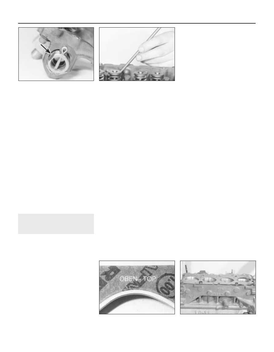
17 Lift out the pushrods. Keep them in order
of fitting by labelling them 1 to 8, starting from
the thermostat end of the cylinder head.
Alternatively, push them through a piece of
card in their fitted sequence (see illustration).
18 Progressively unscrew and loosen off the
cylinder head retaining bolts in the reverse
sequence to that shown for tightening (see
illustration 10.24A). 
When they are all
loosened off, remove the bolts, then lift the
cylinder head clear and remove the gasket.
The gasket must always be renewed; it should
be noted that the cylinder head retaining bolts
may be re-used, but only once. They should
be marked accordingly with a punch or paint
mark. If there is any doubt as to how many
times the bolts have been used, they must be
renewed.
19 To dismantle/overhaul the cylinder head,
refer to Part D of this Chapter. It is normal for
the cylinder head to be decarbonised and the
valves to be reground whenever the head is
removed.

Refitting

20 Prior to refitting the cylinder head, clean
all carbon deposits, dirt and any traces of the
old cylinder head gasket, from the mating
faces of both the head and the cylinder block.
Do not allow any dirt to drop into the cylinder
bores, oil passages or waterways; if any does,
remove it. Clean the threads of the cylinder
head bolts or fit new ones (as applicable) and
clean out the bolt holes in the block. Screwing
a bolt into an oil-filled hole can (in extreme
cases) cause the block to fracture, due to the
hydraulic pressure.
21 If there is any doubt as to the condition of
the exhaust and inlet manifold gaskets, the
manifolds must be removed and the gaskets
renewed, but ensure that the mating faces are
clean before fitting new gaskets.
22 Check that the new cylinder head gasket
is the same type as the original, and that the
“TOP” (or “OBEN”) marking is facing
upwards. Locate the new cylinder head
gasket onto the top face of the cylinder block
and over the dowels. Ensure that it is correctly
aligned with the coolant passages and
oilways 

(see illustrations).

2A•6 HCS engine – in-car engine repair procedures

10.22B  Cylinder head gasket in position on

the top face of the cylinder block

10.22A  Cylinder head gasket top-face

marking (“OBEN”)

10.17  Withdraw the pushrods

9.8  Flat on the rocker shaft (arrowed) to

same side as rocker arm adjusting screws

23 Lower the cylinder head carefully into
position, then insert the retaining bolts and
hand-tighten them.
24 Tightening of the cylinder head bolts must
done in three stages, and in the correct
sequence  (see illustration 10.18). First
tighten all of the bolts in the sequence shown
to the Stage 1 torque setting. When all of the
bolts are tightened to the Stage 1 setting,
further tighten each bolt (in sequence) through
the Stage 2 specified angle of rotation. When
the second stage tightening is completed on
all of the bolts, further tighten them to the
Stage 3 angle setting (in sequence) to
complete. Where possible, use an angular
torque setting gauge attachment tool for
accurate tightening of stages two and three
(see illustrations).
25 Lubricate the pushrods with clean engine
oil, and then insert them into their original
locations in the engine.
26 Refit the rocker shaft assembly. As it is
fitted, ensure that the rocker adjuster screws
engage with their corresponding pushrods.
27 Refit the rocker shaft retaining bolts,
hand-tighten them and then tighten them to
the specified torque wrench setting. As they
are tightened, some of the rocker arms will
apply pressure to the ends of the valve stems,
and some of the rocker pedestals will not
initially be in contact with the cylinder head -
these should pull down as the bolts are
tightened to their specified torque. If for any
reason they do not, avoid the temptation to
overtighten in order to pull them into position;
loosen off the bolts, and check the cause of
the problem. It may be that the rocker adjuster
screws require loosening off in order to allow
the assembly to be tightened down as
required.
28 Adjust the valve clearances as described
in Section 6.
29 Refit the spark plugs and tighten them to
the specified torque (see Chapter 1).
30 Fit a new gasket to the rocker cover, then
refit the rocker cover. Tighten the cover
retaining bolts to the specified torque wrench
setting.
31 The remainder of the refitting procedure is
a reversal of the removal process. Tighten all
fastenings to their specified torque setting

(where given). Refer to the appropriate
Section in Chapter 4 for details on
reconnecting the accelerator and choke
cables. Ensure that all coolant, fuel, vacuum
and electrical connections are securely made.
32 On completion, top-up the engine oil and
coolant levels. When the engine is restarted,
check for any sign of fuel, oil and/or 
coolant leakages from the various cylinder
head joints.

11 Crankshaft pulley 

removal and refitting

1

Removal

Disconnect the battery negative (earth) lead
(refer to Chapter 5, Section 1).
Apply the handbrake, then raise and
support the vehicle at the front end on axle
stands.
Undo the three retaining bolts and remove
the plastic cover from the underside of the
auxiliary drivebelt.
Loosen off the crankshaft pulley retaining
bolt. To prevent the crankshaft from turning,
unbolt and remove the clutch housing cover
plate, and jam the starter ring gear on the
flywheel.
Loosen off the alternator mounting/adjuster
bolts, then pivot the alternator to slacken off
the tension from the auxiliary drivebelt, and
disengage the belt from the crankshaft pulley
(see Chapter 1).
Unscrew and remove the crankshaft pulley
bolt, and withdraw the pulley from the front
end of the crankshaft. If it does not pull off by
hand, lever it free using a pair of suitable
levers positioned diagonally opposite each
other behind the pulley.
If required, the crankshaft front oil seal can
be renewed at this stage, as described in
Section 17.

Refitting

Refitting is a reversal of the removal
procedure. When the pulley is refitted, tighten
the retaining bolt to the specified torque
setting. Relocate the drivebelt over the pulley,

and adjust the tension as described in
Chapter 1.
Refit the drivebelt plastic cover, and lower
the vehicle to complete.

12 Timing chain cover 

removal and refitting

1

Removal

Remove the crankshaft pulley as described
in the previous Section.
A combined timing cover and water pump
gasket is fitted during production; if this is still
in position, it will be necessary to drain the
cooling system and remove the water pump
as described in Chapter 3. If the water pump
and/or the timing cover have been removed at
any time, the single gasket used originally will
have been replaced by an individual item, in
which case the water pump can remain in
position.
Unscrew the retaining bolts, and carefully
prise free the timing chain cover. Note that
two of the retaining bolts also secure the
sump at the front end. Remove the engine
front face-to-cover gasket. If the sump-to-
timing cover gasket is damaged during the
removal of the cover, it will be necessary to
drain and remove the sump in order to renew
the gasket, in which case refer to Section 14
for details.
Clean the mating faces of the timing chain
cover and the engine.
If necessary, renew the crankshaft front oil
seal in the timing cover prior to refitting the
cover (see Section 17).

Refitting

Before refitting the cover into position,
clean the contact faces at the point where the
timing chain cover meets the sump gasket
each side. Smear the faces at this point with
sealant; it is important that a good seal is
made. As previously mentioned, if the sump
gasket is damaged on either side at the front,
it must be renewed (see Section 14) prior to
refitting the timing chain cover.
Lightly lubricate the front end of the

HCS engine – in-car engine repair procedures  2A•7

10.24C  Cylinder head bolt tightening

(Stages 2 and 3) using an angle gauge

10.24B  Tightening the cylinder head bolts

(Stage 1)

10.24A  Cylinder head bolt tightening

sequence

2A

crankshaft and the radial lip of the timing
chain cover oil seal (already installed in the
cover). Using a new gasket, fit the timing
chain cover, centring it with the aid of the
crankshaft pulley (see illustration) - lubricate
the seal contact surfaces beforehand. Where
applicable, leave out the timing cover bolt
which also secures the water pump at this
stage.
Where applicable, refit the water pump as
described in Chapter 3.
Refit the crankshaft pulley as described in
the previous Section. Refer to Chapter 1 for
details on refitting and adjusting the auxiliary
drivebelt.

13 Timing chain, sprockets and

tensioner - removal,
inspection and refitting

3

Removal

Disconnect the battery negative (earth) lead
(refer to Chapter 5, Section 1).
Remove the timing chain cover as
described in the previous Section.
Refer to Section 14 and remove the sump.
Remove the oil slinger from the front face of
the crankshaft, noting its orientation (see
illustration)
.
Retract the chain tensioner cam back
against its spring pressure, then slide the
chain tensioner arm from its pivot pin on the
front main bearing cap (see illustration).

Unbolt and remove the chain tensioner.
Bend back the lockplate tabs from the
camshaft sprocket bolts, then unscrew and
remove the bolts.
Withdraw the sprocket complete with the
timing chain.

Inspection

Examine the teeth on the timing sprockets
for any signs of excessive wear or damage.
10 The timing chain should always be
renewed during a major engine overhaul.
Slack links and pins are indicative of a worn
chain. Unless the chain is known to be
relatively new, it should be renewed.
11 Examine the rubber cushion on the
tensioner spring leaf. If grooved or
deteriorated, it must be renewed.

Refitting

12 Commence reassembly by bolting the
timing chain tensioner into position. Check
that the face of the tensioner cam is parallel
with the face of the cylinder block, ideally
using a dial gauge. The maximum permissible
error between the two measuring points is 0.2
mm. Release and turn the timing chain
tensioner as required to achieve this (if
necessary). Refer to the Specifications for the
correct tightening torque.
13 Turn the crankshaft so that the timing
mark on its sprocket is directly in line with the
centre of the camshaft sprocket mounting
flange.
14 Engage the camshaft sprocket with the
timing chain, then engage the chain around

the teeth of the crankshaft sprocket. Push the
camshaft sprocket onto its mounting flange,
and check that the sprocket retaining bolt
holes are in alignment. Also check that the
timing marks of both sprockets face each
other. If required, turn the camshaft/sprocket
as required to achieve this. It may also be
necessary to remove the camshaft from the
chain in order to reposition it in the required
location in the chain to align the timing marks.
This is a “trial and error” procedure, which
must be continued until the exact alignment of
the bolt holes and the timing marks is made
(see illustrations).
15 Insert and tighten the camshaft sprocket
retaining bolts to the specified torque wrench
setting. Bend up the tabs of the new lockplate
to secure (see illustration).
16 Retract the timing chain tensioner cam,
and then slide the tensioner arm onto its pivot
pin. Release the cam so that it bears on the
arm.
17 Refit the oil slinger to the front of the
crankshaft sprocket so that its convex side
faces the sprocket.
18 Refit the timing chain cover as described
in the previous Section.
19 Refit the sump as described in Section 14.
Top-up the engine oil level as described in
Chapter 1.
20 Reconnect the battery.
21 When the engine is restarted, check for
any sign of oil or coolant leaks from the sump
and water pump (if disturbed).

2A•8 HCS engine – in-car engine repair procedures

13.15  Bend locktabs against the camshaft

retaining bolt heads to secure

13.14B  . . . and check that the timing

marks on the sprockets are in alignment

13.14A  Fit the timing chain to the

crankshaft and camshaft sprockets . . .

13.5  Chain tensioner arm removal from

the pivot pin. Note tensioner retaining

bolts (arrowed)

13.4  Oil slinger removal from crankshaft

12.7  Fitting the timing chain cover.

Crankshaft pulley used as aid to centring

14 Sump - removal and refitting

1

Removal

Disconnect the battery negative (earth) lead
(refer to Chapter 5, Section 1).
Refer Chapter 1 and drain the engine oil.
Refit the sump drain plug.
Undo the retaining nuts and detach the
exhaust downpipe from the manifold flange.
Note that the flange gasket should be
renewed on reassembly. Allowing sufficient
clearance for sump removal, tie the exhaust
downpipe up with a suitable length of wire or
cord to prevent the system straining the
insulators. On catalytic converter-equipped
vehicles, avoid straining the oxygen sensor
wiring, where applicable; if necessary,
disconnect the sensor’s multi-plug.
Remove the starter motor (see Chapter 5).
Undo the two retaining bolts and remove
the clutch housing cover plate.
Undo the eighteen bolts securing the sump
to the base of the engine crankcase, then
prise free and lower the sump. If the sump is
stuck tight to the engine, cut around the
flange gasket with a sharp knife, then lightly
tap and prise it free. Keep the sump upright as
it is lowered, to prevent spillage of any
remaining oil in it. Also be prepared for oil
drips from the crankcase when the sump is
removed.
Remove any dirt and old gasket from the
contact faces of the sump and crankcase, and
wash the sump out thoroughly before refitting.
Check that the mating faces of the sump are
not distorted. Check that the oil pick-up
strainer is clear, cleaning it if necessary.

Refitting

Remove the old gaskets from the timing
chain cover end, and from the flywheel end,
and clean their location faces. Apply a dab of
sealing compound to the mating faces where
the ends of each cork half-gasket are to be
fitted (see illustration). Stick the new cork
gaskets into position on the block face, using
clean thick grease to retain them, then locate

the new rubber gaskets into their slots in the
timing chain cover and rear oil seal carrier.
The lugs of the cork gasket halves fit under
the cut-outs in the rubber gaskets (see
illustration)
.
Before offering up the sump, check that the
gap between the sump and the oil baffle is
between 2.0 and 3.8 mm (see illustration).
Do not use a dented or damaged sump, as
the indicated dimension is important for
correct engine lubrication.
10 Fit the sump into position, and fit the
retaining bolts. Initially tighten them all finger-
tight, then further tighten them in the
sequence shown through Stages 1 and 2, to
the torque wrench settings specified (see
illustration)
. Note that different tightening
sequences are specified for the tightening
stages. Final (Stage 3) tightening is carried out
after the engine has been started and warmed
up.
11 Refit the lower plate to the front face of
the clutch housing.
12 Refit the starter motor.
13 Check that the downpipe and manifold
mating faces are clean, then locate a new
gasket and reconnect the exhaust downpipe
to the manifold. Where applicable, use new
self-locking nuts, and tighten securely.
14 Check that the sump drain plug is fitted
and tightened to the specified torque, then
lower the vehicle to the ground.

15 Top-up the oil level in the sump as
described in Chapter 1 (taking care not to
over-fill).
16 Reconnect the battery, then start the
engine and run it up to its normal operating
temperature. Check that no oil leaks are
evident around the sump joint.
17 After the engine has warmed up for
approximately 15 minutes, switch it off.
Tighten the sump bolts to the Stage 3 torque
wrench setting given in the Specifications, in
the sequence shown in illustration 14.10.

15 Oil pump 

removal and refitting

2

Removal

The oil pump is externally-mounted, on the
rear-facing side of the crankcase.
Apply the handbrake, then raise and
support the vehicle at the front end on axle
stands, allowing sufficient working clearance
underneath.
Unscrew and remove the oil filter cartridge.
It should unscrew by hand, but will probably
be tight. Use a strap wrench to loosen it off, if
required. Catch any oil spillage in a suitable
container.
Undo the three retaining bolts and withdraw
the oil pump from the engine (see
illustration)
.

HCS engine – in-car engine repair procedures  2A•9

14.9  Sump (A) and oil baffle (B) clearance

details

14.8B  Lugs of cork gasket halves to fit

under the cut-outs in the rubber gaskets

14.8A  Sump gasket fitting details at the

timing chain cover end (A) and the flywheel

end (B)

15.4  Unscrewing the oil pump retaining

bolts

14.10  Sump bolt tightening sequence -

arrow indicates crankshaft pulley end of

engine

Refer to Specifications for torque wrench
settings
Stage 1 - Tighten in alphabetical order
Stage 2 - Tighten in numerical order
Stage 3 - Tighten in alphabetical order

2A


Content   ..  8  9  10  11   ..