Ford Festiva. Manual - part 47


  Index      Ford     Ford Festiva - service and repair manual 1991 year


Search            


Content   ..  45  46  47  48   ..


Ford Festiva. Manual - part 47


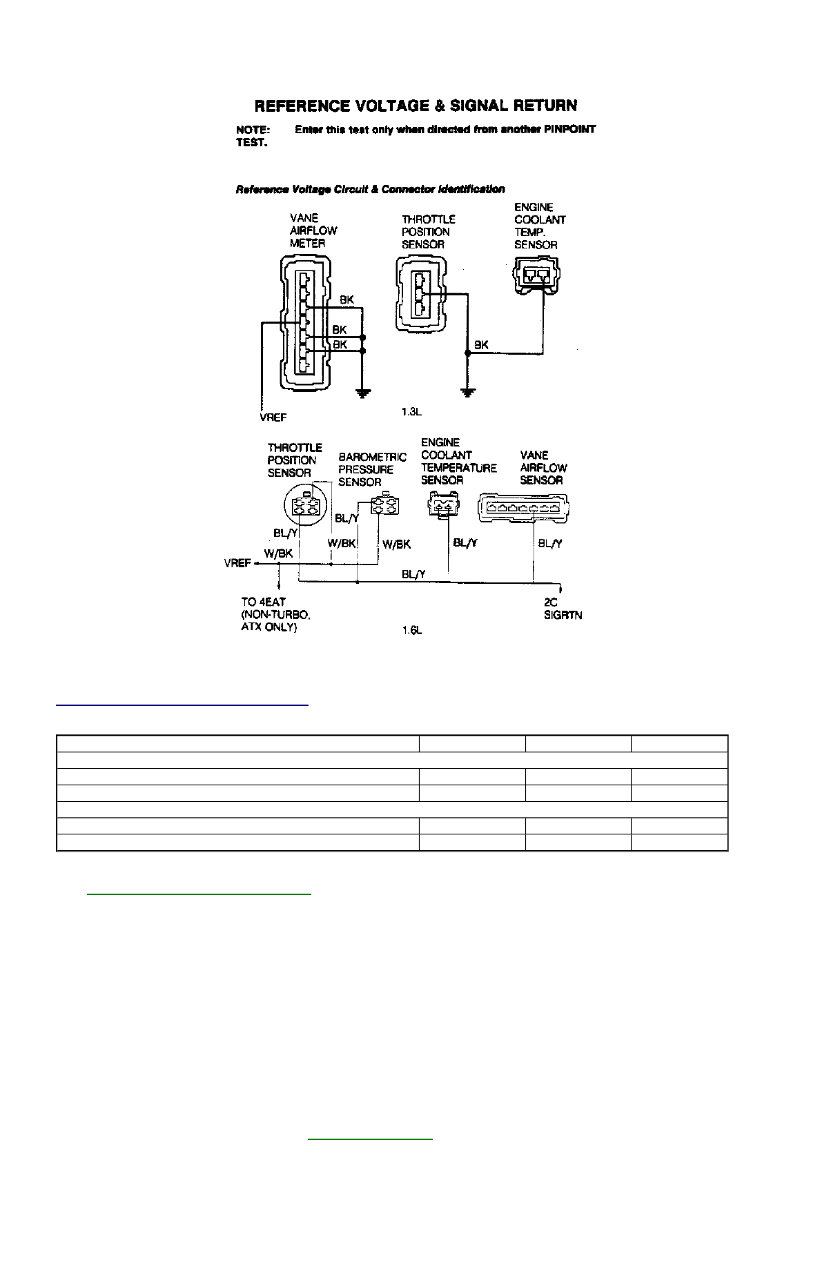
Fig. 18: Identifying VREF Circuit & Connector


VREF CIRCUIT PIN IDENTIFICATION 

1. On 1.3L, go to next step. On 1.6L, turn ignition on. Measure voltage between throttle position switch VREF and SIGRTN wires. See 

VREF CIRCUIT PIN IDENTIFICATION

 table. If voltage is 10-12 volts, repair short to voltage. If voltage is zero volts, go to next 

step.  

2. Turn ignition on. On 1.3L, measure voltage between Black and White-Black wires at VAF sensor. On 1.6L, measure voltage between 

White-Black and Blue/Yellow wires at BP sensor. If voltage is 4-5 volts, VREF circuit is okay. If voltage is zero volts, go to next step. If 
voltage is 10-12 volts, repair short to voltage.  

3. Turn ignition off. Install BOB. Install 4EAT tester (if vehicle is equipped with 4EAT transaxle). Unplug connector from VAF, TP, and 

BP sensors as applicable to vehicle. Measure resistance between VREF terminals on ECA and 4EAT module. Also measure resistance 
between ECA VREF terminal and TP, BP, and VAF VREF harness connector terminals. If any measurement is greater than 5 ohms, 
repair wire in question. If resistance is less than 5 ohms for all measurements, go to next step.  

4. Turn ignition off. Disconnect 4EAT module (if equipped). Unplug connector from VAF, TP, and BP sensors as applicable to vehicle. 

Measure resistance between ECA VREF pin on BOB and ground. If resistance is not greater than 10,000 ohms, repair short in VREF 
circuit. If resistance is greater than 10,000 ohms, go to next step.  

5. Turn ignition off. Disconnect ECA. Unplug connector from VAF, TP, and BP sensors as applicable to vehicle. Measure resistance 

between ECA SIGRTN, 4EAT, and all SIGRTN pins on BOB. If any measurement is greater than 5 ohms, repair wire in question. If 
resistance is less than 5 ohms for all measurements, go to next step.  

6. Turn ignition off. Install BOB. Connect ECA. Connect 4EAT module (if equipped). Turn ignition on. Measure voltage at ECA SIGRTN 

test pin on BOB. If voltage is 0-1 volt, go to 

PINPOINT TEST PGC

 . If voltage is not 0-1 volt, repair short to voltage on SIGRTN 

circuit.  

SUMMARY 

Circuit

ECA Pin

BOB Pin

Wire Color

1.3L

SIGRTN

2D

46, 49

BLK

VREF

2K

26

WHT/BLK

1.6L

SIGRTN

2C

46

BLU/YEL

VREF

2A

26

WHT/BLK

If no hard codes, or only pass codes, are present, and driveability symptoms or intermittent codes still exist, proceed to TESTS W/O CODES 
article in the ENGINE PERFORMANCE Section for diagnosis by symptom (i.e., ROUGH IDLE, NO START, etc.) or intermittent diagnostic 
procedures. 

Copyright 2009 Mitchell Repair Information Company, LLC.  All Rights Reserved. 


Article GUID: A00022768 

Back To Article


H - TESTS W/O CODES 

1991-92 ENGINE PERFORMANCE Ford Motor Co. Trouble Shooting - No Codes 

INTRODUCTION 

Before diagnosing symptoms or intermittent faults, perform steps in BASIC TESTING and TESTS W/CODES articles in the ENGINE 
PERFORMANCE Section. Use this article to diagnose driveability problems existing when a hard fault code is not present or vehicle is not 
equipped with a self-diagnostic system. 

Symptom checks can direct the technician to malfunctioning component(s) for further diagnosis. A symptom should lead to a specific 
component, system test or adjustment. 

Use intermittent test procedures to locate driveability problems which DO NOT occur when the vehicle is being tested. These test procedures 
should also be used if a soft (intermittent) trouble code was present but no problem was found during self-diagnostic testing. 

SYMPTOMS 

SYMPTOM DIAGNOSIS 

Symptom checks cannot be used properly unless problem occurs while vehicle is being tested. To reduce diagnostic time, ensure steps in 
BASIC TESTING and TESTS W/CODES articles in the ENGINE PERFORMANCE Section were performed before diagnosing a symptom. 
These symptoms are available for diagnosis. 

Backfire through induction or exhaust.  

Dieseling (run-on).  

Lack of power.  

Spark knock (pinging).  

Stalls/quits.  

Stumble/hesitation during acceleration.  

Misses/surges.  

Idle is fast/slow return to idle.  

Idle is rough.  

Engine speeds up.  

Cranks normally/no start.  

Cranks normally/slow to start.  

Poor fuel economy.  

Exhaust smoke/odor.  

Fuel odor/leaks.  

Fails emission test.  

BACKFIRE THROUGH INDUCTION OR EXHAUST 

Check vane airflow meter.  

Check idle speed control solenoid.  

DIESELING (RUN-ON) 

Check idle speed control solenoid.  

LACK OF POWER 

Check vane airflow meter.  

Check throttle position switch.  

Check heated exhaust gas oxygen sensor.  

Check A/C switch.  

Check wide open throttle A/C (WAC) relay.  

SPARK KNOCK (PINGING) 

Verify ignition timing is correct.  

Check vane airflow meter.  

STALLS/QUITS 

NOTE:

Some driveability problems may have been corrected by manufacturer with a revised computer 
calibration chip or computer control unit. Check with manufacturer for latest chip or computer 
application.

NOTE:

For specific testing procedures, see SYSTEM/COMPONENT TESTS article in the ENGINE 
PERFORMANCE Section. For specifications, see ADJUSTMENTS or SPECIFICATIONS article in the 
ENGINE PERFORMANCE Section.

Check vane airflow meter.  

Check idle speed control solenoid.  

Check pressure regulator control solenoid.  

Check heated exhaust gas oxygen sensor.  

Check engine coolant temperature sensor.  

Check A/C load control solenoid.  

STUMBLE/HESITATION DURING ACCELERATION 

Check throttle position switch.  

Check vane airflow meter.  

Check canister purge solenoid.  

Check heated exhaust gas oxygen sensor.  

Check wide open throttle A/C (WAC) relay.  

Check A/C thermostatic switch.  

MISSES/SURGES 

Check exhaust gas oxygen sensor.  

Check throttle position switch.  

Check vane airflow meter.  

Check wide open throttle vacuum switch.  

Check A/C load control solenoid.  

Check engine coolant temperature sensor.  

IDLE IS FAST/SLOW RETURN TO IDLE 

Check idle speed control solenoid.  

Check by-pass air control valve.  

Check engine coolant temperature sensor.  

Check A/C load control solenoid.  

IDLE IS ROUGH 

Check idle speed control solenoid.  

Check A/C load control solenoid.  

Check by-pass air control valve.  

Check throttle position switch.  

Check vane airflow meter.  

Check vane air temperature sensor.  

Check canister purge solenoid.  

Check engine cooling fan.  

Check headlight switch.  

Check blower control switch.  

Check A/C thermostatic switch.  

Check neutral safety switch.  

Check neutral gear switch or clutch engage switch.  

Check heated exhaust gas oxygen sensor.  

ENGINE SPEEDS UP 

Check idle speed control solenoid.  

Check heated exhaust gas oxygen sensor.  

Check by-pass air control valve.  

CRANKS NORMALLY/NO START 

Verify secondary ignition spark is present.  

Verify fuel pressure is within specification.  

Check vane airflow meter.  

Check engine coolant temperature sensor.  

CRANKS NORMALLY/SLOW TO START 

Check ignition module.  

Check engine coolant temperature sensor.  

Check vane airflow meter.  

Check evaporative emission control components.  


Content   ..  45  46  47  48   ..