Content .. 1529 1530 1531 1532 ..
Ford F150 Pickup. Manual - part 1531
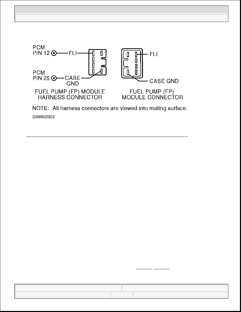
Fig. 274: Identifying Fuel Pump Module Circuits & Connector Terminals (ZX2)
Courtesy of FORD MOTOR CO.
81) Check FLI Circuit For Short To VPWR In Harness
Turn ignition switch to OFF position. Disconnect PCM connector(s). Turn ignition switch to ON position.
Using a DVOM, measure voltage between negative battery terminal and FLI circuit at fuel pump module
harness connector. If voltage is more than 10.5 volts, repair short to VPWR in FLI circuit. If voltage is
10.5 volts or less, replace PCM.
82) Check FLI Circuit For Short To PWR GND In Harness
Turn ignition switch to OFF position. Disconnect PCM connector(s). Using a DVOM, measure resistance
between negative battery terminal and FLI circuit at PCM harness connector. If resistance is more than 10
k/ohms, go to next step. If resistance is 10 k/ohms or less, repair short to PWR GND in FLI circuit.
83) Check FLI Circuit For Short To CASE GND In Harness
Using a DVOM, measure resistance between CASE GND and FLI circuits at PCM harness connector. If
resistance is more than 10 k/ohms, go to step 85). If resistance is 10 k/ohms or less, repair short between
FLI and CASE GND circuits.
85) Check FLI Circuit For Open In Harness
Using a DVOM, measure resistance of FLI circuit between PCM harness connector, fuel pump module
connector (pigtail), and instrument cluster connector. See Fig. 271-Fig. 274 . For instrument cluster
connector and terminal identification, see appropriate INSTRUMENT PANELS article in
ACCESSORIES & EQUIPMENT. If both resistance measurements are less than 10 ohms, go to next
2003 Ford Pickup F150
2003 ENGINE PERFORMANCE Self-Diagnostics - CNG, Flex-Fuel & Gasoline