Daewoo Korando. Service manual - part 260


  Index      Daewoo     Daewoo Korando - service and repair manual


Search            


Content   ..  258  259  260  261   ..


Daewoo Korando. Service manual - part 260


AUTOMATIC TRANSMISSION  5A-83

Tightening Torque

70 - 80 Nm

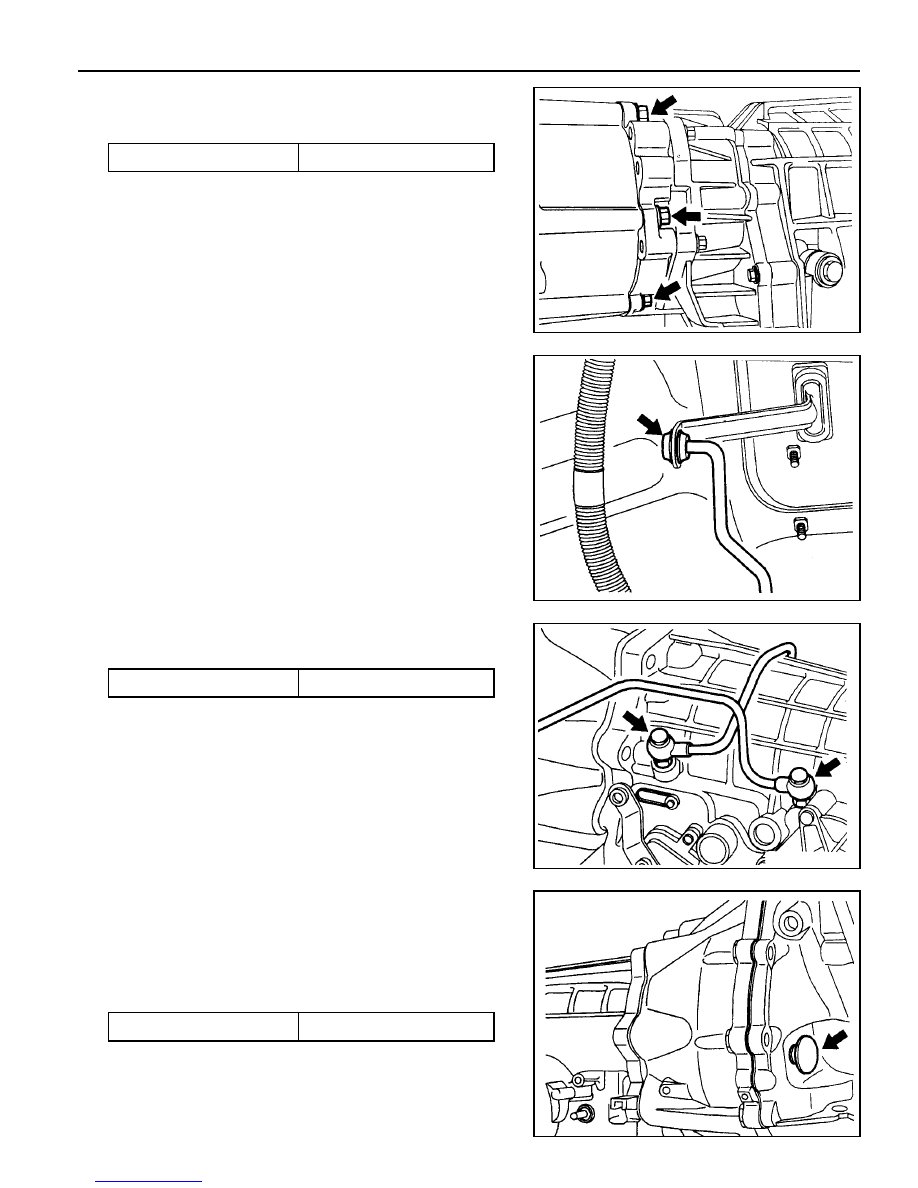
11. Remove the two pipes for oil cooler.

Installation Notice

Tightening Torque

24.5 - 34.3 Nm

12. Remove the service hall cover on torque converter.

13. Put the alignment mark for installation, and unscrew the

six mounting bolts for torque converter from drive plate
through the service hole (arrow) by rotating the engine
and remove the torque converter.

Installation Notice

Tightening Torque

42 Nm

7. Remove the rear propeller shaft.

Installation Notice

8. Unscrew the five bolts and remove the transfer case.

9. Disconnect the 10-Pins Plug connector from transmission.

10. Separate the locking clip on shift lever and remove the

shift rod.

Notice

Removal and installation performed when the shift
procedure should be lever is in “D” range.

Screw the six bolts mounting the torque converter through
the service hole by using a mirror and rotating the engine.

5A-84  AUTOMATIC TRANSMISSION

Tightening Torque

55 - 65 Nm

14. Remover the starter.

15. Unscrew the eight transmission housing bolts and remove

the transmission assembly.

Installation Notice

Be careful not to drop the torque converter while removing
the transmission.

16. Installation should follow the removal procedure in the

reverse order.

AUTOMATIC TRANSMISSION  5A-85

UNIT REPAIR

REBUILD WARNINGS

Prior to rebuilding a transmission system, the following warnings
are to be noted.

l

Ensure that, before replacing a transmission the cooler

lines are flushed out to remove any debris. This can be
done by applying compressed air to the rear cooler line
forcing oil and any contaminants out of the front cooler
line.

l

The cooler flow should be checked after the transmission

has been fitted. With the front cooler line connected
and the rear line run into a suitable container, measure
the flow over 15 seconds with the vehicle idling in park.

l

The flow rate should exceed 1 liter in 15 seconds.

l

Be wary of any situation where water enters the

transmission. This may result in fluid foaming and leaking
through the breather.

l

Ensure that both earth straps (one at the batted terminal

and one on the vehicle body) are connected in the
vehicle before connecting the positive side of the
battery.

l

Follow the throttle position calibration procedure in

section 7 of this manual if the powertrain control module
transmission control unit (PCM/TCU) is swapped.

DISASSEMBLY PROCEDURE

Transmission

Notice

Remove the inhibitor switch before washing the transmission
in solvent or hot wash.

It is assumed that the transmission fluid has been drained
when the transmission was removed from the

vehicle and that the ‘special tools’ quoted are available.

The transmission is dismantled in a modular fashion, and the
details of disassembly for each module are given under the
appropriate subject. Refer to table 9.10 in section 9.6 for details
of all special tools required when performing disassembly
procedures.

Technicians overhauling these transmissions will also require
a selection of good quality Torx bit sockets, in particular
numbers 30, 40 and 50, and an 8 mm,10 mm and 12 mm
double hex socket.

To disassemble the transmission, proceed as follows:

1. Remove the converter and the converter housing.

2. Mount the transmission on the bench cradle

No.0555-331895.

3. Remove the sump and the sump seal.

5A-86  AUTOMATIC TRANSMISSION

9. Remove the pump to case bolts using a multi-hex 8 mm

spanner.

10. Using the pump puller No. 0555-332941, remove the pump.

11. Remove the input shaft, forward clutch cylinder, and the

overdrive shaft as an assembly, withdrawing them through
the front of the case.

12. Remove the C3 clutch cylinder and sun gears.

13. Remove the fronts band struts. Remove the front band.

14. Remove the two centre support retaining bolts using a

T50 Torx bit.

15. Remove the centre support retaining circlip.

Notice

Do not hammer the output shaft to remove the centre
support as this will cause permanent damage to the thrust
bearing surfaces.

16. Remove the centre support, 1-2 one way clutch, planetary

gear set and output shaft as an assembly.

17. Remove the parking rod cam plate. (T40 Torx bit).

18. Remove the rear band struts and remove the band.

4. Detach each end of the filter retaining clip from the valve

body and remove the filter.

5. Detach the wires from each solenoid and lay the wiring to

one side.

6. Remove the valve body securing screws and remove the

valve body from the case.

7. Remove the front servo cover circlip.

Remove the cover and piston.

Notice

The plastic servo block is retained by the piston return
spring only.

8. Where fitted, remove the flange yoke, and then remove

the extension housing (RWD model).

Remove the adaptor housing (4WD model).


Content   ..  258  259  260  261   ..