Daewoo Korando. Service manual - part 227


  Index      Daewoo     Daewoo Korando - service and repair manual


Search            


Content   ..  225  226  227  228   ..


Daewoo Korando. Service manual - part 227


HYDRAULIC BRAKES  4A-9
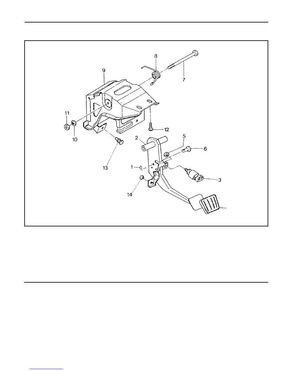
BRAKE PEDAL

1 Clevis Pin
2 Brake Pedal
3 Stop Lamp Switch
4 Pad
5 Nut ....................................................... 21-35 Nm
6 Yoke Pin
7 Fulcrum Pin

8 Return Spring
9 Pedal  Mounting Bracket

10 Washer

11 Nut ....................................................... 16-32 Nm

12 Bolt ........................................................ 8-18 Nm
13 Stopper Bolt .............................................. Adjust
14 Rubber Pad ........................................... Replace

4A-10  HYDRAULIC BRAKES

Removal & Installation Procedure

1. Remove the stop lamp switch connector.

2. Remove the clevis pin and disconnect the brake booster

push rod.

Notice

l

Install in the upper hole (1), in case of Mando brake and

in the below hole (2), incase of PBR brake.

l

Install the snap pin fully in the hole of clevis pin.

l

Apply the grease around the hole of clevis pin.

3. Loosen the nut (4EA) and bolt (2EA) and remove the brake

pedal.

4. Installation should follow the removal procedure in the

reverse order.

Tightening Torque

8 - 18 Nm

HYDRAULIC BRAKES  4A-11

Adjustment Procedure

1. Pedal Height

Notice

If pedal height is not in specified value, loosen the stop
lamp nut (B) and adjust the pedal height.

2. Pedal Stroke

Height (A)

150 mm (From the carpet)

Notice

If pedal stroke is not in specified value, loosen the stop bolt
and lock nut (F) and adjust the pedal stroke.

3. Free Play

Stroke (C)

Mando : 138 mm

PBR : 132 mm

Notice

To adjust, depress the brake pedal several times until there
is no more vacuum left in the vacuum line.

To adjust, loosen the lock nut (D) of the push rod and turn
the rod.

Free Play (E)

1 - 4 mm

Inspection Procedure

1. Inspect the wear of bushing.

2. Inspect the warp and bend of brake pedal.

3. Inspect the return spring of brake pedal.

4. Inspect the conductivity when connecting the tester to the

stop lamp switch connector.

4A-12  HYDRAULIC BRAKES

LCRV (LOAD CONSCIOUS REDUCING VALVE)

1 Brake Tube (from the master cylinder)
2 Brake Tube (from the rear brake)
3 LCRV Bracket
4 Bolt ........................................................... 12 Nm

5 LCRV Assembly
6 Connecting Link
7 Spring Washer
8 Nut ....................................................... 14-18 Nm


Content   ..  225  226  227  228   ..