Daewoo Korando. Service manual - part 193


  Index      Daewoo     Daewoo Korando - service and repair manual


Search            


Content   ..  191  192  193  194   ..


Daewoo Korando. Service manual - part 193


 M162 ENGINE INTAKE & EXHAUST  1G1-5
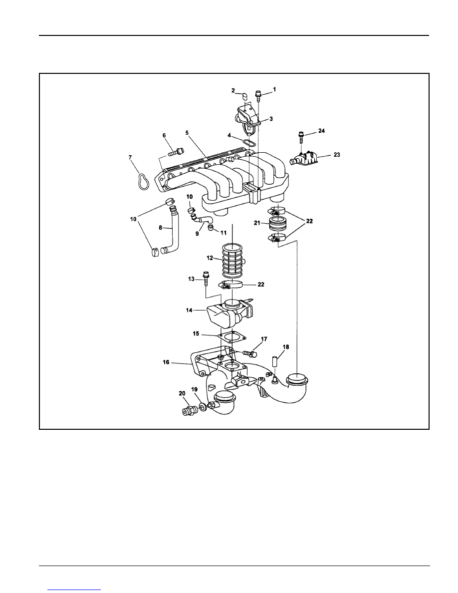
INTAKE MANIFOLD

Preceding Work : Removal of fuel distributor and injection valve

1 Bolt (M6 X 40, 4 pieces) ......................... 9-11 Nm
2 Softcap
3 Resonance Flap
4 Gasket ................................................... Replace
5 Upper Intake Manifold
6 Bolt (M8 x 50, 9 pieces) ................. 22.5-27.5 Nm
7 Gasket ................................................... Replace
8 Blow-by Hose
9 Blow-by Hose

10 Clamp

11 Blow-by Nipple

12 Inlet Air Housing

13 Bolt (M6 x 40, 4 pieces) ......................... 9-11 Nm
14 Throttle Body - Electric
15 Gasket ................................................... Replace
16 Lower Intake Manifold .........................................
17 Bolt (M8 x 40, 4 pieces) ................. 22.5-27.5 Nm
18 Nipple .................................................... Replace
19 Seal Ring
20 Connection House
21 Clamp
22 Noise Damper Assembly
23 Tapping Screw

1G1-6  M162 ENGINE INTAKE & EXHAUST

Removal & Installation Procedure

l

Upper Intake Manifold

1. Disconnect the vacuum hose (8,9).

2. Loosen the clip (22).

3. Remove the upper intake manifold (5) after unscrewing the

bolt (6).

Installation Notice

Notice

Check the gasket and replace it if necessary.

4. Installation should follow the removal procedure in the

reverse order.

l

Lower Intake Manifold

Preceding work : removal of upper intake manifold

1. Remove the hose of brake booster vacuum line and idle

speed connector.

2. Disconnect the hot water inlet pipe from the bottom of lower

intake manifold.

3. Unscrew the bolt (17) and remove the lower intake manifold

(16).

Installation Notice

4. Start the engine and check for leaks at each connection

part.

Tightening  Torque

22.5 - 27.5 Nm

Tightening  Torque

22.5 - 27.5 Nm

 M162 ENGINE INTAKE & EXHAUST  1G1-7

RESONANCE FLAP

1 Soft Cap (2)
2 Bolt (M6 x 25, 4 pieces) ......................... 9-11 Nm
3 O-ring

Removal & Installation Procedure

1. Remove the 2 soft caps (1).

2. Remove the upper resonance flap coupling after removing

4 bolts (2).

Notice

Connect carefully the vacuum hose (4) for installation.

3. Check the O-ring (3) and replace it if necessary.

4. Remove the lower resonance flap (5).

5. Replace the gasket (6).

6. Installation should follow the removal procedure in the

reverse order.

4 Vacuum Hose
5 Resonance Flap
6 Gasket ................................................... Replace

1G1-8  M162 ENGINE INTAKE & EXHAUST

Function Description

A pneumatically actuated resonance flap (5) is located on the
intake manifold, and will be opened and closed by load, which
operates resonance flap according to engine and controlled
by ECU and rpm.

1. Resonance flap closed (at idle/partial load : less than

3,800/rpm)

The switch valve (7) will be adjusted by ECU and resonance
falp will be colosed. By increasing air flow passage through
dividing intaking air flow toward both air collection housing
(8). This leads to a signficant increase in the torque in the
lower speed range.

2. Resonance flap open (at full load : over 3,800/rpm)

The switch valve (7) will not be adjusted by ECU and
resonance falp (5) will be open. The colllected air in the air
collection housing (8) will not be divided and intaking air
passage will be shorten.


Content   ..  191  192  193  194   ..