Daewoo Nubira. Service manual - part 254


  Index      Daewoo     Daewoo Nubira - service and repair manual


Search            


Content   ..  252  253  254  255   ..


Daewoo Nubira. Service manual - part 254


2E – 8

I

TIRES AND WHEELS

DAEWOO V–121 BL4

GENERAL DESCRIPTION

AND SYSTEM OPERATION

TIRE AND WHEEL BALANCING

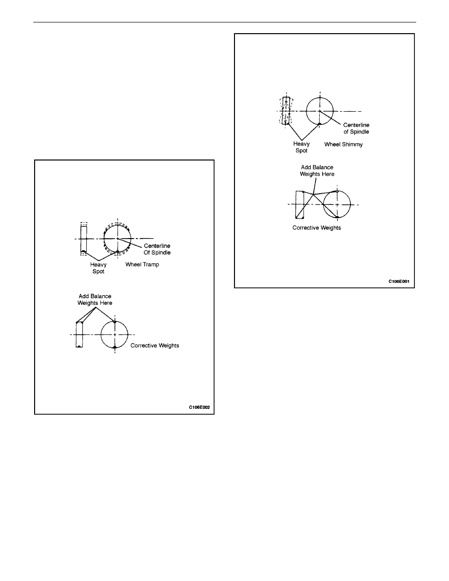
There are two types of tire and wheel balancing: static and
dynamic.

Static balance is the equal distribution of weight around
the wheel. Assemblies that are statically unbalanced
cause a bouncing action called wheel tramp. This condi-
tion may eventually cause uneven tire wear.

Dynamic balance is the equal distribution of weight on
each side of the centerline so that when the assembly
spins there is no tendency for it to move from side to side.
Assemblies that are dynamically unbalanced may cause
wheel shimmy.

General Balance Precautions

Remove all deposits of foreign material from the inside of
the wheel.

CAUTION :  Remove stones from the tread in order to
avoid operator injury during spin balancing.

Inspect the tire for any damage. Balance the tire according
to the equipment manufacturer

s recommendations.

WheelWeights

If more than 85 grams (3.0 ounces) are needed to static
balance the wheel, split the wheel weights as equally as
possible between the inboard and the outboard flanges.

Balancing the assemblies with factory alloy wheels re-
quires the use of special nylon–coated, clip–on wheel
weights. These weights are designed to fit over the thicker
rim flange of the alloy wheel. Install these weights with a
plastic–tipped hammer.

Adhesive wheel weights are also available. Use the follow-
ing procedure to install adhesive wheel weights.

TIRES AND WHEELS  2E – 9

DAEWOO V–121 BL4

Adhesive WheelWeight Installation

1.  Clean the wheel by sanding it to bare alloy where

the wheel weight will be installed.

2.  Use a clean cloth or paper towel saturated with

amixture of half isopropyl alcohol and half water to
wipe the place where the wheel weight will be
installed.

3.  Dry the area with hot air. The surface of the wheel

should be warm to the touch.

4.  Warm the adhesive backing on the wheel weights

to room temperature.

5.  Remove the tape from the back of the weights. Do

not touch the adhesive surface.

6.  Apply the the wheel weight and press it on with

hand pressure.

7.  Secure the wheel weight with a 70–110 N (16–25

lb) force applied with a roller.

TIRE CHAIN USAGE

Due to limited tire–to–body clearance on certain vehicles,
recommendations for tire chain use are published in the
Owner’s Manual. When tire chains need to be used, most
current Daewoo vehicles require SAE Class”S” tire
chains. These may also be designated as 1100 Series,
type PL tire chains. These chains are specifically designed
to limit the”fly off”effect which occurs when the wheel ro-
tates.

Be sure that only fine–link chains are used which do not
addmore than 15 mm (0.590 inch), including the lock, to
the tread surface and the inner sides of the tires. Manufac-
turers of tire chains have a specific chain size for each tire
size to ensure a proper fit when the chain is installed. Be
sure to purchase the correct chains for the tires on which
they are to be used. Use rubber adjusters to take up any
slack or clearance in loose chains.

Use of chains may adversely affect vehicle handling.

When tire chains are installed, follow these precautions:

S


Adjust speed to road conditions.

S


Avoid sharp turns.

S


Avoid locked–wheel braking.

To prevent chain damage to the vehicle, install the chains
on the front tires as tightly as possible. Tighten them again
after driving 0.4 to 0.8 kilometer (0.3 to 0.5 mile). The use
of chains on the rear tires is not recommended because
they may contact the vehicle and possibly damage it. If
chains must be used on the rear tires, be sure there is suffi-
cient clearance between the chains and the body. Do not
exceed 70 km/h (45 mph) or the chain manufacturer’s
speed limit, if lower. Avoid large bumps, potholes, severe
turns and any other maneuvers which could cause the
tires to bounce. Follow any other instructions of the chain
manufacturer which do not disagree with the above in-
structions.

REPLACEMENT TIRES

A tire performance criteria (TPC) specification number is
molded in the sidewall near the tire size of all original
equipment tires. This specification number assures that
the tire meets performance standards for traction, endur-
ance, dimensions, noise, handling and rolling resistance.
Usually a specific TPC number is assigned to each tire
size.

CAUTION :  Do not mix different types of tires on the
same vehicle such as radial, bias and bias–belted
tires except in emergencies, because vehicle han-
dling may be seriously affected and may result in loss
of control.

Use only replacement tires with the same size, load range,
and construction as the original. The use of any other tire
size or construction type may seriously affect ride, han-
dling, speedometer/odometer calibration, vehicle ground
clearance, and tire clearance to the body and the chassis.
This does not apply to the spare tire furnished with the ve-
hicle.

It is recommended that new tires be installed in pairs on
the same axle.

If it is necessary to replace only one tire, pair it with the tire
having the most tread to equalize the braking action.

Although they may appear different in tread design, tires
built by different manufacturers with identical TPC specifi-
cations may be used on the same vehicle.

ALL SEASON TIRES

Most vehicles are now equipped with steel–belted all sea-
son radial tires as standard equipment. These tires qualify
as snow tires, with a 37 percent higher average rating for
snow traction than the non–all season radial tires pre-
viously used. Other performance areas, such as wet trac-
tion, rolling resistance, tread life, and air retention, have
also been improved. This was done by improvements in
both tread design and tread compounds. These tires are

2E – 10

I

TIRES AND WHEELS

DAEWOO V–121 BL4

identified by an ’M + S”molded in the tire sidewall following
the size number. The suffix ”MS”is also molded in the side-
wall after the TPC specification number.

The optional handling tires used on some vehicles are not
all season tires. These will not have the”MS”marking after
the tire size or the TPC specification number.

PASSENGER METRIC SIZED TIRES

All Daewoo vehicles now use Passenger (P) metric sized
tires. P–metric tires are available in two load ranges: stan-
dard load (35 psi maximum) and extra load (41 psi maxi-
mum). Most passenger vehicle tires are standard load.

Most P–metric tire sizes do not have exact corresponding
alphanumeric tire sizes. For example, a P175/70R13 is
not exactly equal in size and load–carrying capacity to an
FR70–13. For this reason, replacement tires should be of
the same TPC specification number as the originals. If P–
metric tires must be replaced with other sizes, consult a
tire dealer. Tire companies can best recommend the clos-
est match of alphanumeric to P–metric sizes within their
own tire lines.

The metric term for measuring tire inflation pressure is the
kilopascal (kPa). Tire pressure may be printed in both kPa
and psi. One psi equals 6.895 kPa.

See the tire label or refer to 


Tire Size and Pressure Speci-

fications

"

in this section for tire inflation pressures

TIRE LABEL

The tire label is permanently located on the rear face of the
driver

s door and should be referred to for tire information.

It lists the maximum vehicle load, the tire size (including
the spare tire), and the cold inflation pressure (including
the spare tire).

SPARE TIRE

This vehicle comes equipped with a reduced–sized tem-
porary tire on a steel wheel

WHEELS

Wheels must be replaced if they are bent, dented, have
excessive lateral or radial runout, leak air through welds,
have elongated bolt holes, or if the wheel bolts won’t stay
tight or are heavily rusted. Wheels with excessive runout-
may cause vehicle vibration. Replacement wheels must
be equivalent to the original equipment wheels in load ca-
pacity, diameter, rim width, offset, and mounting configu-
ration. Awheel of improper size or typemay affect wheel

and bearing life, brake cooling, speedometer/ odometer
calibration, vehicle ground clearance, and tire clearance
to the body and the chassis. The wheel offset is 49 + 1 mm
(1.93 + 0.04 inches). Steel wheels may be identified by a
two– or three–letter code stamped into the rim near the
valve stem. Alloy wheels should have the code, the part
number, and themanufacturer ID cast into the back side.

INFLATION OF TIRES

The pressure recommended for any vehicle line is careful-
ly calculated to give a satisfactory ride, handling, tread life,
and load–carrying capacity.

Tire pressure should be checked monthly or before any
extended trip. Check the tires when they are cold, after the
vehicle has sat for 3 hours or more, or has been driven less
than 1 mile. Set the tire pressure to the specifications on
the tire label located on the rear face of the driver

s door.

Tire inflation pressure is also given under ”Tire Size and
Pressure Specifications” in this section.

Valve caps or extensions should be on the valves to keep
dust and water out.

For sustained driving at speeds up to 140 km/h (85 mph),
inflate the tires to the pressure recommended on the tire.
Sustained driving at speeds faster than 140 km/h (85
mph), even if permitted by law, is not advised unless the
vehicle has special high–speed tires available from many
tire dealers. Tire pressures may increase as much as 41
kPa (6 psi) when the tires are hot.

Higher than recommended tire pressure can cause

S

 Hard 

ride.

S


Tire bruising or damage.

S


Rapid tread wear at the center of the tire.

Lower than recommended pressure can cause

S


Tire squeal on turns.

S

 Hard 

steering.

S


Rapid and uneven wear on the edges of the tread.

S


Tire rim bruises and rupture.

S


Tire cord breakage.

S

 High 

tire 

temperatures.

Unequal tire pressures on same axle can cause

S

 Uneven 

braking.

S

 Steering 

lead.

S

 Reduced 

handling.

S


Swerve on acceleration.

S

 Torque 

steer.

SECTION : 2B

WHEEL ALIGNMENT

TABLE OF CONTENTS

SPECIFICATIONS

2B–1

. . . . . . . . . . . . . . . . . . . . . . . . . . 

WHEEL ALIGNMENT SPECIFICATIONS

2B–1

. . . . . 

DIFFERENCE BETWEEN LEFT AND RIGHT

2B–1

FASTENER TIGHTENING SPECIFICATIONS

2B–1

DIAGNOSIS

2B–2

. . . . . . . . . . . . . . . . . . . . . . . . . . . . . . . . 

TIRE DIAGNOSIS

2B–2

. . . . . . . . . . . . . . . . . . . . . . . . . 

RADIAL TIRE LEAD/PULL

2B–3

. . . . . . . . . . . . . . . . . . 

VIBRATION DIAGNOSIS

2B–5

. . . . . . . . . . . . . . . . . . . 

PRELIMINARY INSPECTION

2B–9

. . . . . . . . . . . . . . . 

FRONT TOE ADJUSTMENT

2B–9

. . . . . . . . . . . . . . . . 

FRONT CAMBER AND CASTER CHECK 

2B–9

. . . . 

REAR CAMBER CHECK

2B–10

. . . . . . . . . . . . . . . . . . 

REAR TOE ADJUSTMENT

2B–10

. . . . . . . . . . . . . . . . 

GENERAL DESCRIPTION AND SYSTEM

OPERATION 

2B–11

. . . . . . . . . . . . . . . . . . . . . . . . . . . . 

FOUR WHEEL ALIGNMENT

2B–11

. . . . . . . . . . . . . . . 

TOE 2B–11

. . . . . . . . . . . . . . . . . . . . . . . . . . . . . . . . . . . . 

CASTER 2B–11

. . . . . . . . . . . . . . . . . . . . . . . . . . . . . . . . 

CAMBER

2B–11

. . . . . . . . . . . . . . . . . . . . . . . . . . . . . . . . 

STEERING AXIS INCLINATION

2B–11

. . . . . . . . . . . . 

INCLUDED ANGLE

2B–11

. . . . . . . . . . . . . . . . . . . . . . . 

SCRUB RADIUS

2B–11

. . . . . . . . . . . . . . . . . . . . . . . . . 

SETBACK

2B–11

. . . . . . . . . . . . . . . . . . . . . . . . . . . . . . . 

TURNING ANGLE

2B–11

. . . . . . . . . . . . . . . . . . . . . . . . 

SPECIFICATIONS

WHEEL ALIGNMENT SPECIFICATIONS

Application

Front

Rear

Camber

–24’ 

µ

 45

³

–50’ 

µ

 45

³

Caster

3

³


µ

 45

³

Toe–in (2–person load)

–0

³


µ

 10’

3’ 

µ

 45’

Note : The above alignment specifications are with the vehicle in a normally loaded condition. Prior to inspection or align-
ment, place a weight of approximately 150 lbs. (68 kg) on each front seat cushion.

DIFFERENCE BETWEEN LEFT AND RIGHT

Application

Front

Rear

Camber

1

³

max

30’ max

Caster

1

³

max

Toe–in

15’ max

FASTENER TIGHTENING SPECIFICATIONS

Application

N

S

m

Lb–Ft

Lb–In

Rear Parallel Link–to–Crossmember Bolt

75

55


Content   ..  252  253  254  255   ..