Daewoo Nubira. Service manual - part 244


  Index      Daewoo     Daewoo Nubira - service and repair manual


Search            


Content   ..  242  243  244  245   ..


Daewoo Nubira. Service manual - part 244


2D – 18

I

REAR SUSPENSION

DAEWOO V–121 BL4

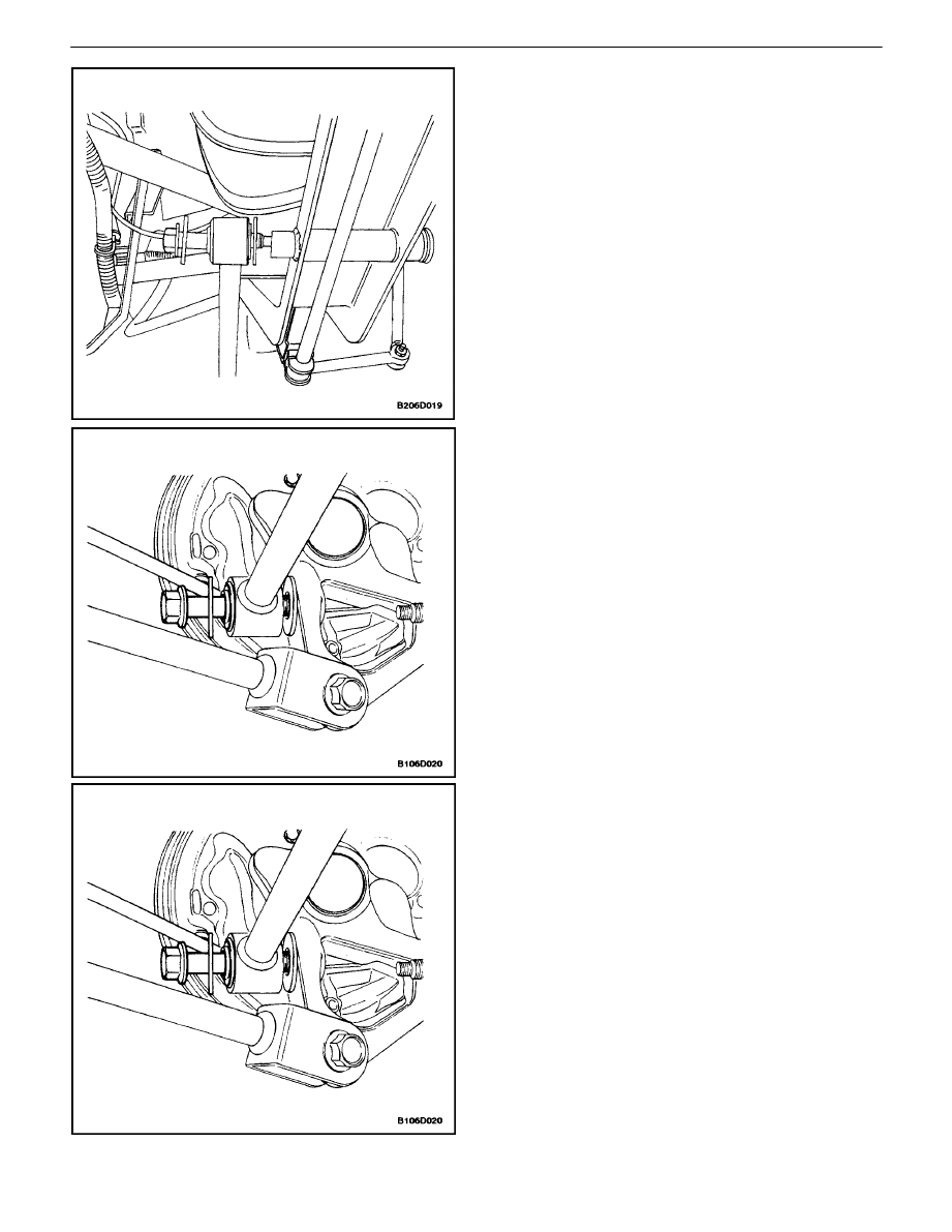
4.  Remove the front parallel link bolt from the rear

rossmember.

5.  Remove the front parallel link bolt from the rear

knuckle.

6.  Remove the front parallel link.

Installation Procedure

1.  Install the front parallel link.
2.  Install the front parallel link onto the rear knuckle

with the bolt.

Tighten

Tighten the front parallel link–to–knuckle bolt to 90
N

S

m (66 lb–ft).

REAR SUSPENSION  2D – 19

DAEWOO V–121 BL4

3.  Install the front parallel link onto the rear cross-

member with the bolt.

Tighten

Tighten the front parallel link–to–crossmember bolt to
90 N

S

m (66 lb–ft).

4.  For vehicles equipped with the antilock braking sys-

tem, install the ABS housing assembly onto the
front parallel link and the ABS sensor line into the
knuckle.

5.  Install the wheel. Refer to Section 2E, Tires and

Wheels.

6.  Lower the vehicle.

REAR PARALLEL LINK

Removal Procedure

1.  Raise and suitably support the vehicle.
2.  Remove the wheel. Refer to Section 2E, Tires and

Wheels.

Important : Before removing the parallel link–to–cross-
member bolt, mark the position of the adjuster cam in rela-
tion to the parallel link and the crossmember. This adjuster
cam must be placed in the same position when the parallel
link is installed on the vehicle to maintain the proper rear
toe.

3.  Remove the rear parallel link bolt from the rear

crossmember.

2D – 20

I

REAR SUSPENSION

DAEWOO V–121 BL4

4.  Remove the rear parallel link bolt from the rear

knuckle.

5.  Remove the rear parallel link.

Installation Procedure

1.  Install the rear parallel link.
2.  Install the rear parallel link–to–knuckle bolt.

Tighten

Tighten the rear parallel link–to–knuckle bolt to 90
N

S

m (66 lb–ft).

3.  Install the rear parallel link onto the rear crossmem-

ber. Install the rear parallel link–to–crossmember
bolts. Do not tighten.

4.  Install the wheel. Refer to Section 2E, Tires and

Wheels.

5.  Perform a rear toe adjustment. Refer to Section 2B,

Wheel Alignment.

REAR SUSPENSION  2D – 21

DAEWOO V–121 BL4

STABILIZER SHAFT

Removal Procedure

1.  Raise and suitably support the vehicle.
2.  Remove the stabilizer shaft clamp bolts.

3.  Remove the stabilizer shaft–to–stabilizer link nut.
4.  Remove the stabilizer shaft clamps, the insulators,

and the stabilizer shaft from the vehicle.

Installation Procedure

1.  Install the stabilizer shaft, the insulators, and the

stabilizer shaft clamps.

2.  Install the stabilizer shaft–to–stabilizer link nut.

Tighten

Tighten the stabilizer shaft–to–stabilizer link nut to 47
N

S

m (35 lb–ft).


Content   ..  242  243  244  245   ..